

An implementation method and device for switching master and slave controller
An implementation method and controller technology, applied in the field of communication, can solve the problems of complex device implementation, and achieve the effects of reducing system cost, simplifying system design, and reducing design requirements
- Summary
- Abstract
- Description
- Claims
- Application Information
AI Technical Summary
Problems solved by technology
Method used
Image

Examples
Embodiment Construction
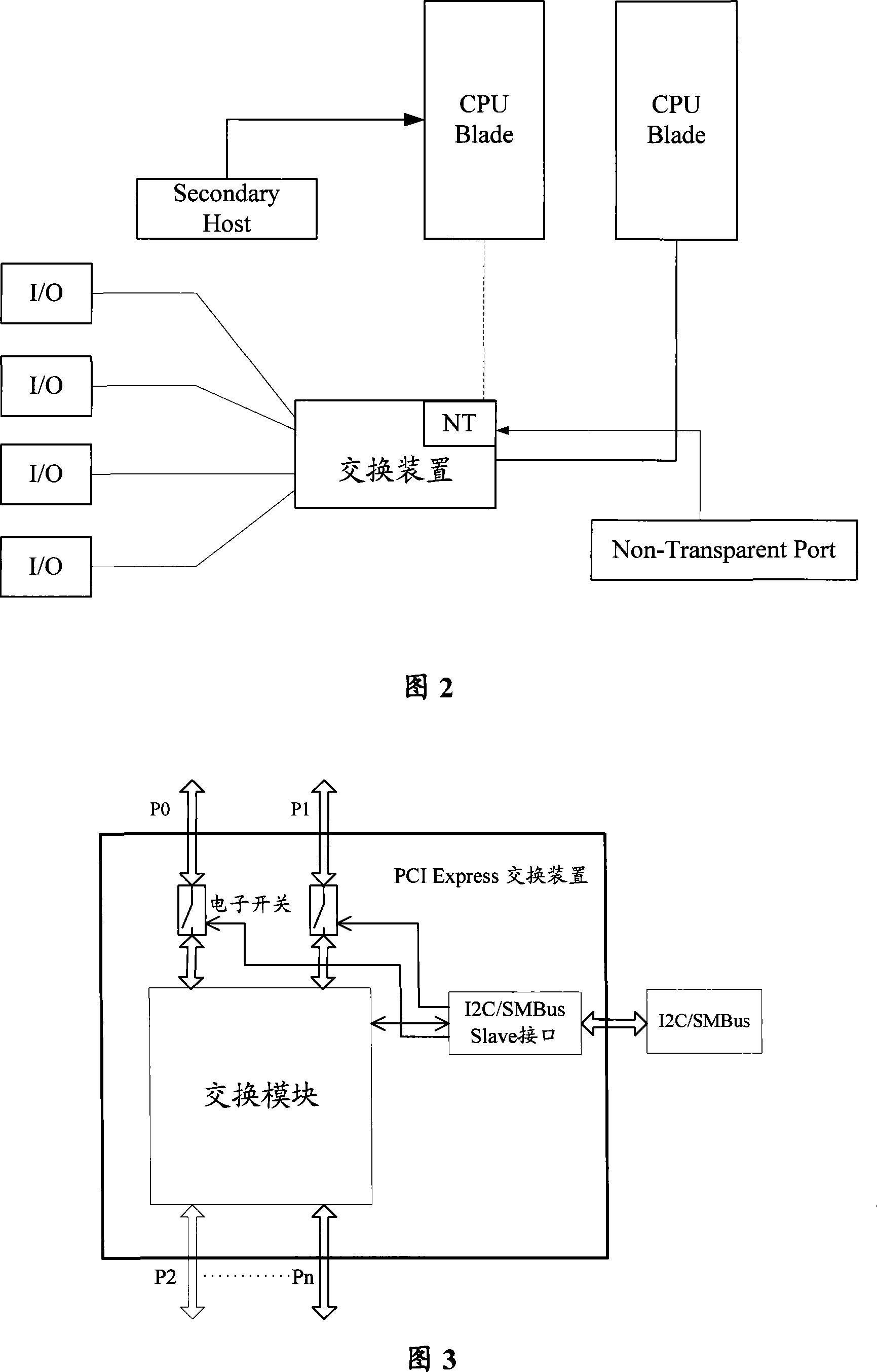
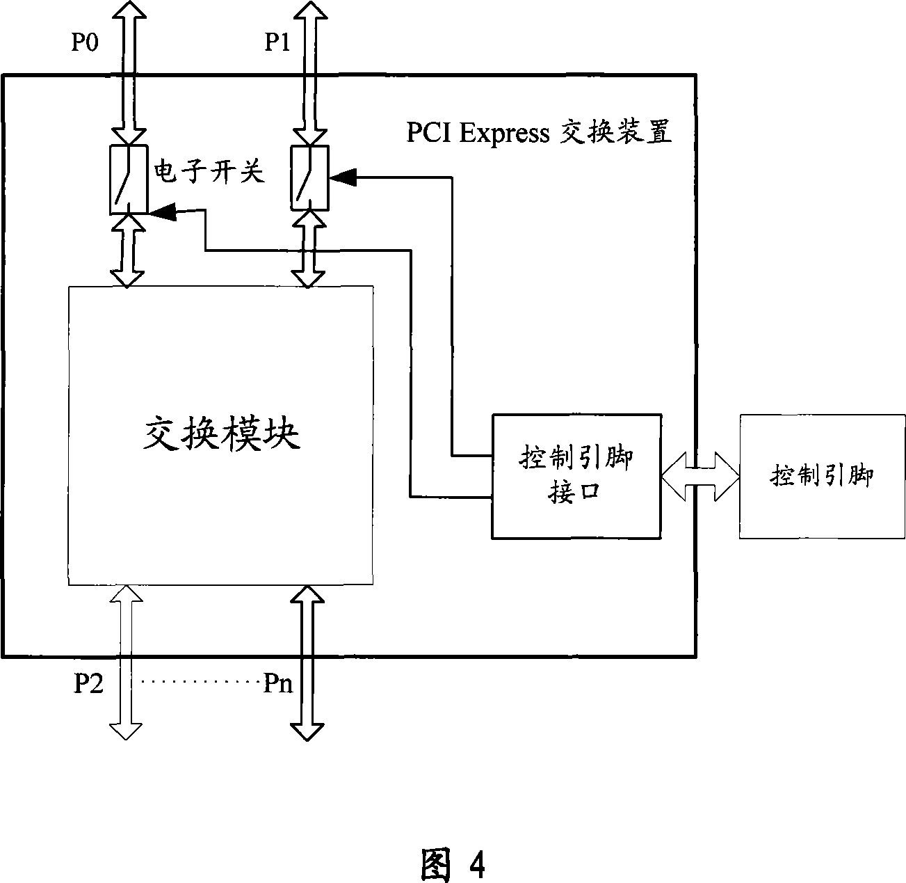
[0050] The present invention provides an active / standby controller switchover system, comprising: a switching device, a multi-way switch module and at least two control devices, the control devices are mutually active and standby, and each have a root multiplexer with the function of connecting to a PCIE link . Wherein, the switching device specifically includes: a switching module, a switching module and a switching control module; the switching module includes at least two uplink ports and a plurality of downlink ports, and the uplink ports are respectively connected to the root multiplexer of the corresponding control device through the switch module, and the downlink The port is connected to the downstream equipment; the switch control module is connected to the switch module, and is used to control the conduction of the switch module connected to the root multiplexer of the main control device when the main control device is working, and to multiplex with the root of the b...
PUM
 Abstract
Description
Claims
Application Information