Mechanical arm

A technology of manipulators and rotating shafts, applied in the direction of manipulators, chucks, manufacturing tools, etc., can solve the problems of inability to complete free rotation around the arm shaft and inaccurate positioning, and achieve convenient and fast grasping operations, simple structure, and high work efficiency Effect

Inactive Publication Date: 2008-01-16
钱成
View PDF0 Cites 11 Cited by
  • Summary
  • Abstract
  • Description
  • Claims
  • Application Information

AI Technical Summary

Problems solved by technology

[0003] Existing manipulators, excavators, hoisting machines, and steel grabbers, whether electric or hydraulic, have manipulators (operating claws for manipulators, buckets for excavators, and grab buckets and truck cranes for steel grabbers). The hook) usually can only swing up and down, and can open and close at most, but cannot complete the 360° free rotation around the axis of the arm, so that in the actual application process, it cannot be accurately positioned to grab the object, which brings a lot of trouble to the actual production. so much inconvenience

Method used


Image

  • Mechanical arm
  • Mechanical arm

Examples


Embodiment

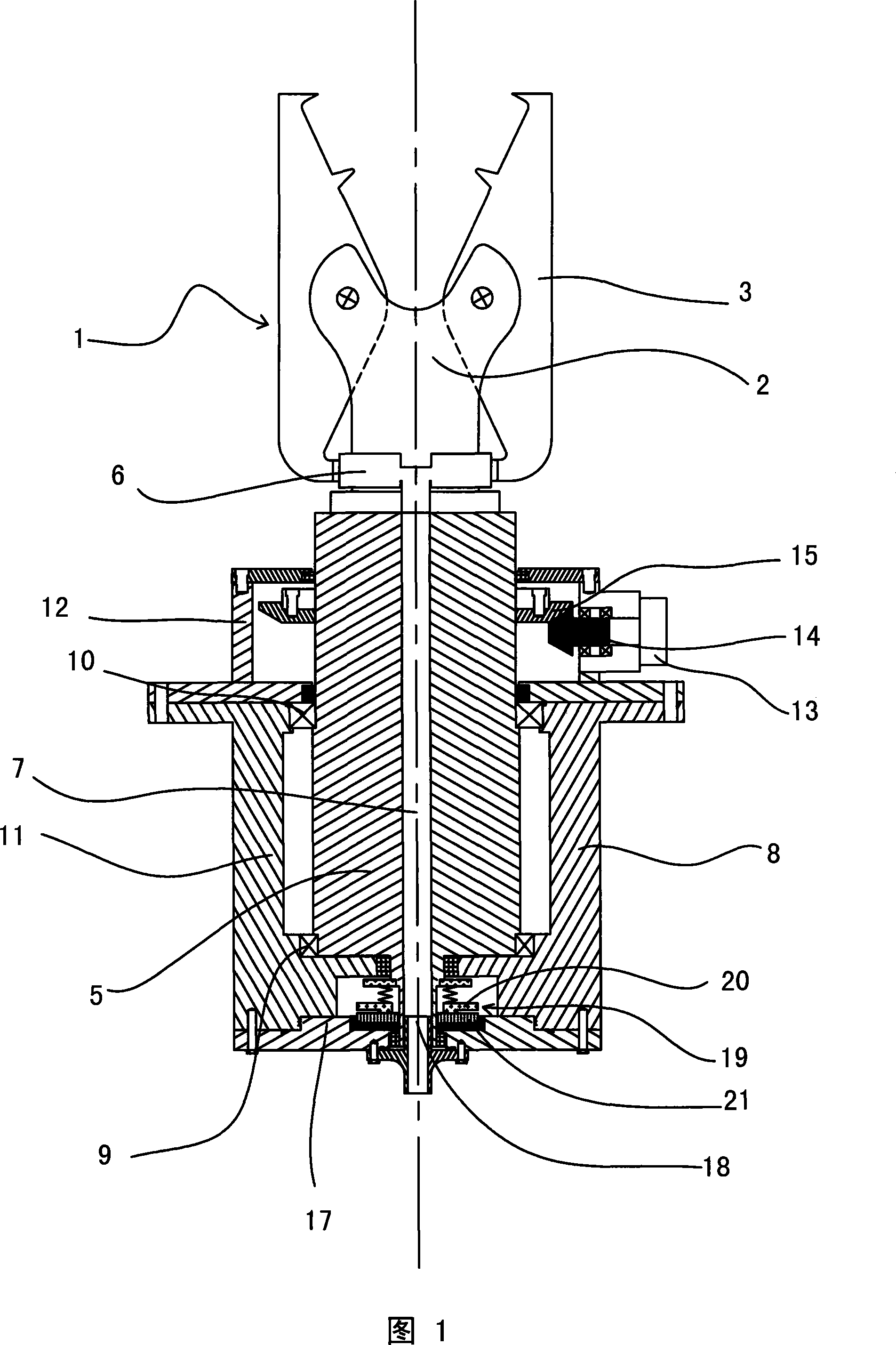
[0025] Embodiment: Referring to the accompanying drawing 1, a manipulator includes three parts: a claw 1 , a rotating shaft 5 and a shaft cylinder 8 .

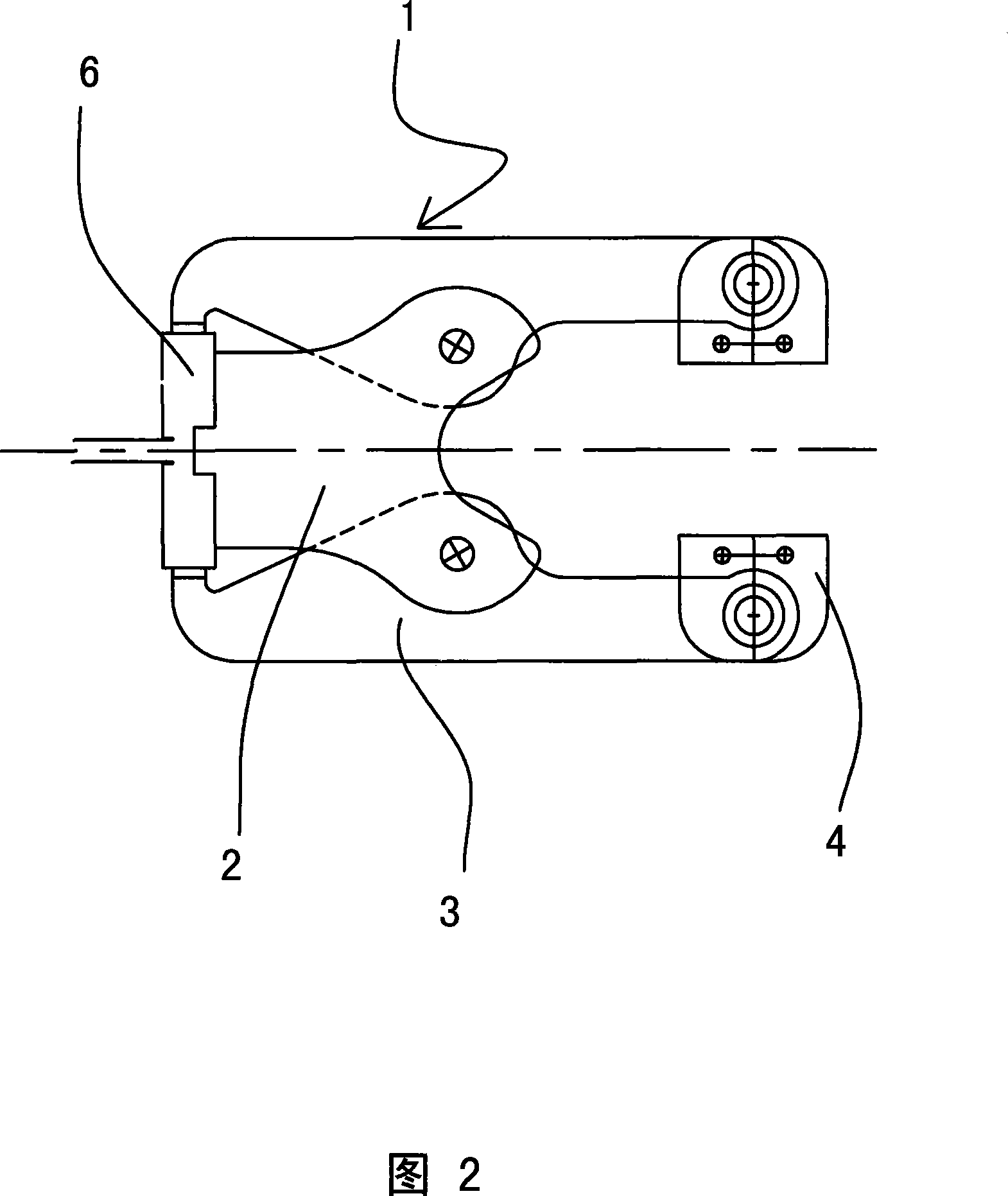
[0026] Referring to the accompanying drawing 1, the claw portion 1 is composed of a bracket 2 and two claws 3, the inner sides of the two claws 3 are provided with sharp teeth (as shown in Figure 1), and the claws 3 can also be hinged at the front end Claw surface is the claw head 4 (referring to accompanying drawing 2) of the curved surface of the suitable blank shape of band anti-skid tooth. Two finger claws 3 are symmetrical to the central axis of support 2 and are hinged on the protruding part of support 2 with the middle part, and the rear end of support 2 is connected to the rotating shaft 5 with the center of the axis, and the rear part of support 2 or the front part of rotating shaft 5 correspond to two The tail ends of the finger claws 3 are fixedly connected to a hydraulic cylinder 6 respectively, and the pistons of ...


PUM


Abstract

Disclosed is a manipulator, which is characterized in that the invention comprises three parts: a jaw, a shaft and a beam-barrel. The jaw comprises a bracket and at least two claws. The middle parts of the two claws are hinged on the bracket whose back end is connected with the shaft. A hydraulic cylinder is respectively arranged at the rear end of the two claws. Pistons of the two hydraulic cylinders are connected with corresponding rear ends of the claws. The center of the shaft is provided with oil supplying holes which are respectively connected with the two hydraulic cylinders so as to form a lever-type grasping mechanism. The shaft is rotationally supported inside the beam-barrel. A first umbrella-shaped gear arranged on the output shaft of a hydraulic motor meshes with a second umbrella-shaped gear which is correspondingly connected on the shaft so that a rotating mechanism where the jaw can rotate around the shaft by 360 degrees is formed. The manipulator has characteristics of reasonable design, high performance price ratio, simple structure, convenient using, high work efficiency and good reliability.

Description

technical field [0001] The invention relates to the field of mechanical equipment, in particular to a hydraulic manipulator. As an operating part, the hydraulic manipulator can be widely used in manipulators, hoisting machines, and steel grabbing machines in the construction industry and industrial and agricultural production industries. Background technique [0002] In the existing construction industry, industrial and agricultural production industries, the emergence and use of manipulators, excavators, hoisting machines, and steel grabbers have improved the degree of modernization of production, reduced labor intensity, and doubled production efficiency. [0003] Existing manipulators, excavators, hoisting machines, and steel grabbers, whether electric or hydraulic, have manipulators (operating claws for manipulators, buckets for excavators, and grab buckets and truck cranes for steel grabbers). The hook) usually can only swing up and down, and can open and close at most,...

Claims


Application Information

Patent Timeline
Patent Type & Authority Applications(China)
IPC IPC(8): B25J3/00B25J15/00B25J19/00
Inventor 钱成
Owner 钱成
Why Eureka
Try Eureka