

Fast slip casting technique between composite well wall
A technology of grouting and shaft wall, which is applied in sinking, shaft equipment, mining equipment, etc., can solve the problems of poor safety conditions, high cost, and low efficiency, and achieve the effect of fast grouting speed, low cost, and high efficiency
- Summary
- Abstract
- Description
- Claims
- Application Information
AI Technical Summary
Problems solved by technology
Method used
Image

Examples
Embodiment 1
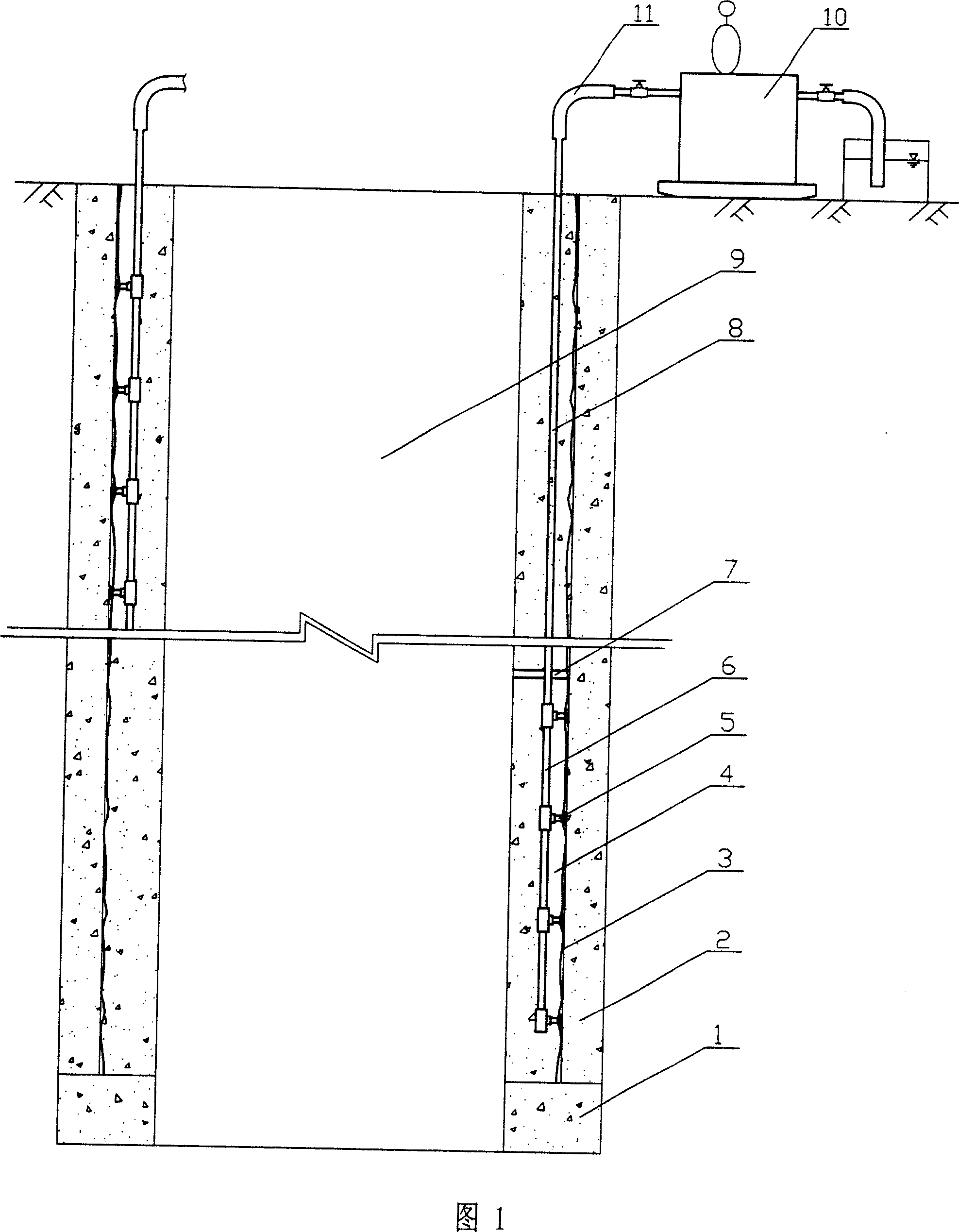
[0011] As shown in FIG. 1 , the composite well wall is composed of an outer well wall 2 , an inner well wall 4 , and a plastic interlayer wall 3 . The grouting pump 10 is fixed on the surface of the wellhead. Before grouting, the wellbore is segmented according to the depth of the frozen wellbore, the thickness of the well wall, the strength, and the level of the aquifer. Generally, the wellbore is divided into 1-4 grouting segments. The section height is generally 100-200m. When constructing the inner shaft wall 4, the vertical section grouting pipe 6 suitable for the height of the grouting section is preset and pre-embedded, and the section grouting pipe 6 is set inside In the well wall of each layer, the preset and pre-embedded vertical segmented grouting pipes are sequentially carried out upwards from above the wall seat 1. A number of grouting heads 5 are arranged on the segmented grouting pipe 6, and the distance between the grouting heads 5 is 5-7 meters. The grouting h...
Embodiment 2
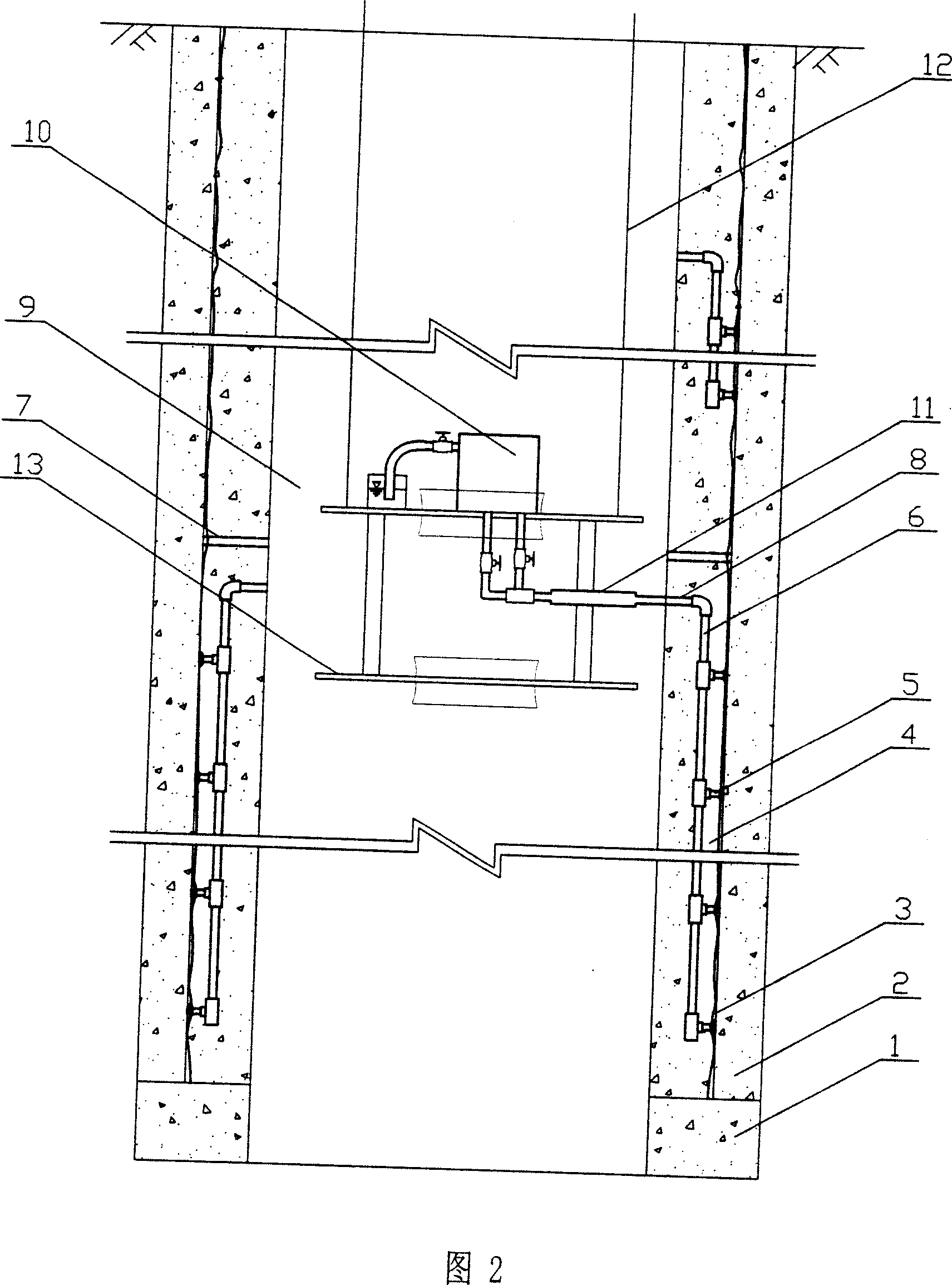
[0013] As shown in FIG. 2 , the composite well wall is composed of an outer well wall 2 , an inner well wall 4 , and a plastic interlayer wall 3 . The grouting pump 10 is fixed on the hanging pan 13 in the wellbore 9, and the hanging pan 13 is pulled by four hanging pan wire ropes 12. Slurry segmentation, generally divide the wellbore into 2-3 grouting segments, and the segment height is generally 100-200m. When constructing the inner well wall 4, the preset, pre-embedded and grouting segment heights are suitable The vertical segmental grouting pipe 6 is arranged in the inner shaft wall 4, and the vertical segmental grouting pipes are preset and pre-embedded starting from above the wall seat 1 and proceeding upwards sequentially. A plurality of grouting heads 5 are arranged on the segmented grouting pipe 6, and the distance between the grouting heads is 5-7 meters. The grouting heads 5 communicate with the plastic interlayer walls 3, and multiple grouting points are simultaneo...
PUM
 Abstract
Description
Claims
Application Information