Intelligent bearing with compound sensor

A composite sensor and bearing technology, applied in the direction of shaft and bearing, bearing components, bearing assembly, etc., can solve the problems of assembly difficulty, stress concentration, poor wire layout, etc., and achieve the effect of reasonable layout, simple signal transmission and processing circuit

Active Publication Date: 2008-01-16
CHONGQING UNIV
View PDF0 Cites 21 Cited by
  • Summary
  • Abstract
  • Description
  • Claims
  • Application Information

AI Technical Summary

Problems solved by technology

[0006] However, due to key issues such as where the sensing element is embedded in the bearing and the reasonable arrangement of the sensing device on the composite sensor, the embedded application is limited.
The embedded structure currently used is to concentrate the sensing device on the bearing, which will cause stress concentration, and the wires are not well arranged, which brings difficulties to assembly

Method used


Image

  • Intelligent bearing with compound sensor
  • Intelligent bearing with compound sensor
  • Intelligent bearing with compound sensor

Examples


Embodiment

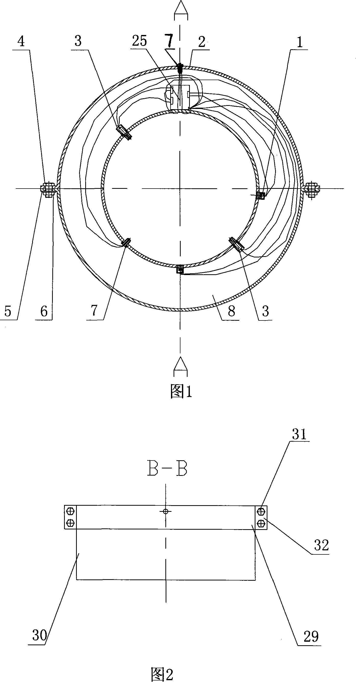
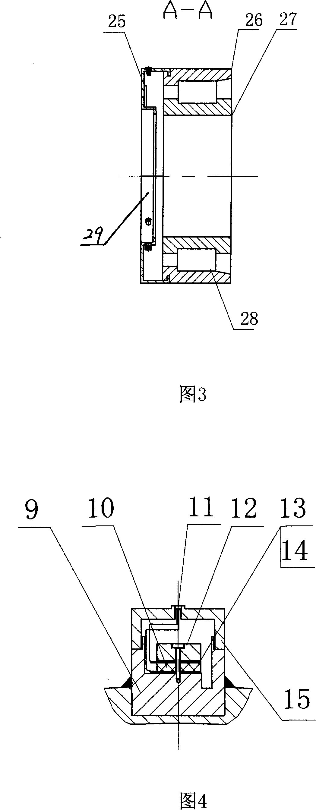
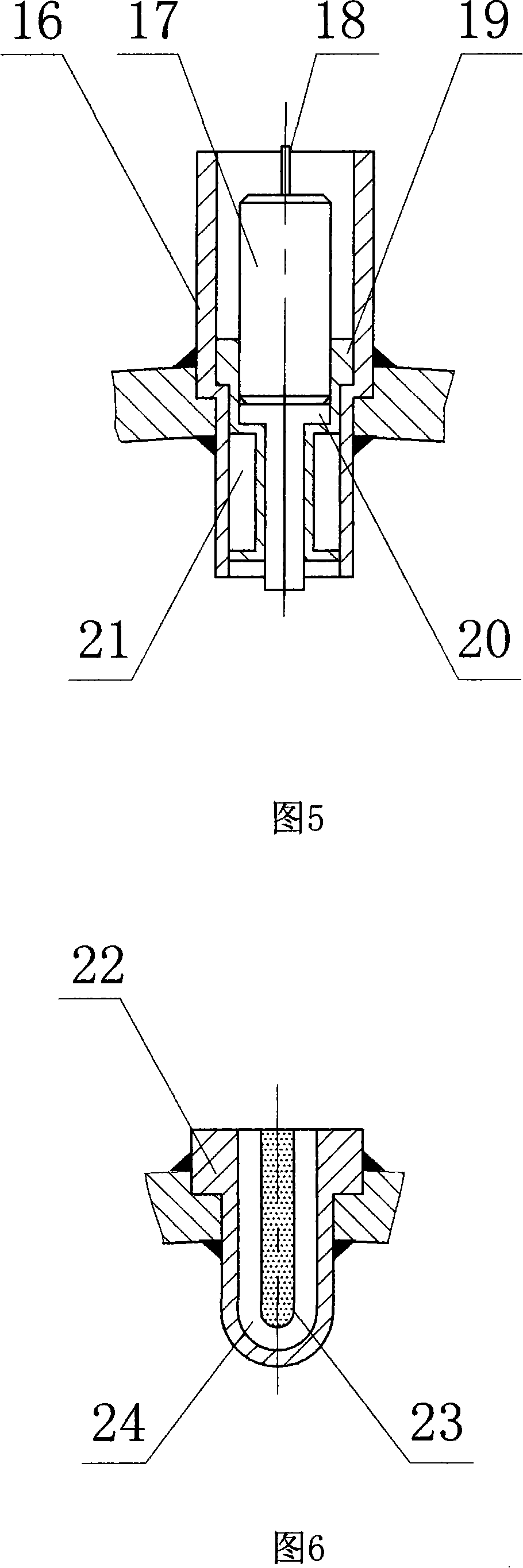
[0037] Please refer to Fig. 1, Fig. 2, Fig. 3, the present invention mainly consists of a bearing 30 and a composite sensor 29 installed on the end face of the bearing 30, the composite sensor is docked by two upper semicircular shells 2 and lower semicircular shells 8 of the same shape A disc housing with a through hole in the center is formed. The inner and outer rings of the disc housing are bent and extended in the same direction to form bosses, and a circuit board 25 is installed on the housing between the two bosses. An acceleration sensing device 1, a speed sensing device 3, and a temperature sensing device 7 are embedded on the boss of the inner ring of the disc housing, and another Temperature sensing device 7 ; the output lines of the sensing devices 1 , 3 , 7 are respectively connected to the input terminals of the amplifiers on the circuit board 25 , and the signals are output after being processed by the amplifiers.

[0038] As shown in Figure 1: two acceleration ...


PUM


Abstract

The invention relates to an intelligent bearing with compound sensor, wherein a compound sensor (29) is arranged at the end surface of a bearing (30). The invention is characterized in that the compound sensor is a circular disk shell composed of an upper semicircular shell (2) and a lower semicircular shell (8) and with a through-hole in the center, the inner ring and outer ring of the circular disk shell both axially extend toward the same direction in bending manner to form a boss respectively, a circuit board (25) is disposed on the shell between the two bosses, an accelerated speed sensing device (1), a speed sensing device (3) and a temperature sensing device (7) are embedded on the boss in the inner ring of the circular disk shell, and another temperature sensing device (7) is disposed on the circumferential surface of the outer ring of the circular disk shell; and output lines of the sensing devices are respectively connected with the amplifier input terminal of the circuit board (25), and the signal is outputted after processing by the amplifier. The invention integrates the vibration sensing device, temperature sensing device and speed sensing device, and can effectively acquire trouble signal of bearing.

Description

technical field [0001] The present invention relates to a sensor, in particular, relates to a kind of on-line monitoring and failure applied to the axles of high-speed railway vehicles (high-speed passenger cars, etc.) The diagnostic system is a compound sensor that can extract the vibration, temperature and speed signals of high-speed train axle bearings, high-end cars and large truck bearings. Background technique [0002] Bearing, as one of the key parts in mechanical equipment, its running state will directly affect the running state and performance of the equipment. The monitoring and fault detection of bearings, especially the main shaft system of large-scale electromechanical equipment and bearings on high-speed vehicles, has become an important research content and application field of fault diagnosis technology. It has been proven that the performance of a bearing diagnostic system depends on its ability to detect faults in the early stage of bearing operation, tha...

Claims


Application Information

Patent Timeline
Patent Type & Authority Applications(China)
IPC IPC(8): F16C41/00
Inventor 邵毅敏葛亮方杰平
Owner CHONGQING UNIV
Why Eureka
Try Eureka