Supercharge Your Innovation With Domain-Expert AI Agents!

Chain transmission device

一种链传动、链轮的技术,应用在传动装置、卷扬装置、便携式提升装置等方向,能够解决振动以及噪音变大、振动噪音变大、制造成本增加等问题,达到降低制造成本、振动以及噪音降低、噪音降低的效果

Inactive Publication Date: 2008-01-16
TSUBAKIMOTO CHAIN CO
View PDF1 Cites 5 Cited by
  • Summary
  • Abstract
  • Description
  • Claims
  • Application Information

AI Technical Summary

Problems solved by technology

For this reason, there is a problem that the vibration and noise at the start of meshing of the subsequent roller 2 become large
For this reason, there is a problem that vibration and noise at a specific meshing frequency corresponding to the rotational speed become larger
[0021] In addition, since the roller chain transmission disclosed in the above-mentioned Japanese Patent Laid-Open No. 2005-163806 uses sprockets having at least first teeth and second teeth with different tooth shapes, there is a problem that the tooth shape is complicated and its manufacturing cost increases. question

Method used


Image

  • Chain transmission device
  • Chain transmission device
  • Chain transmission device

Examples


Embodiment 1

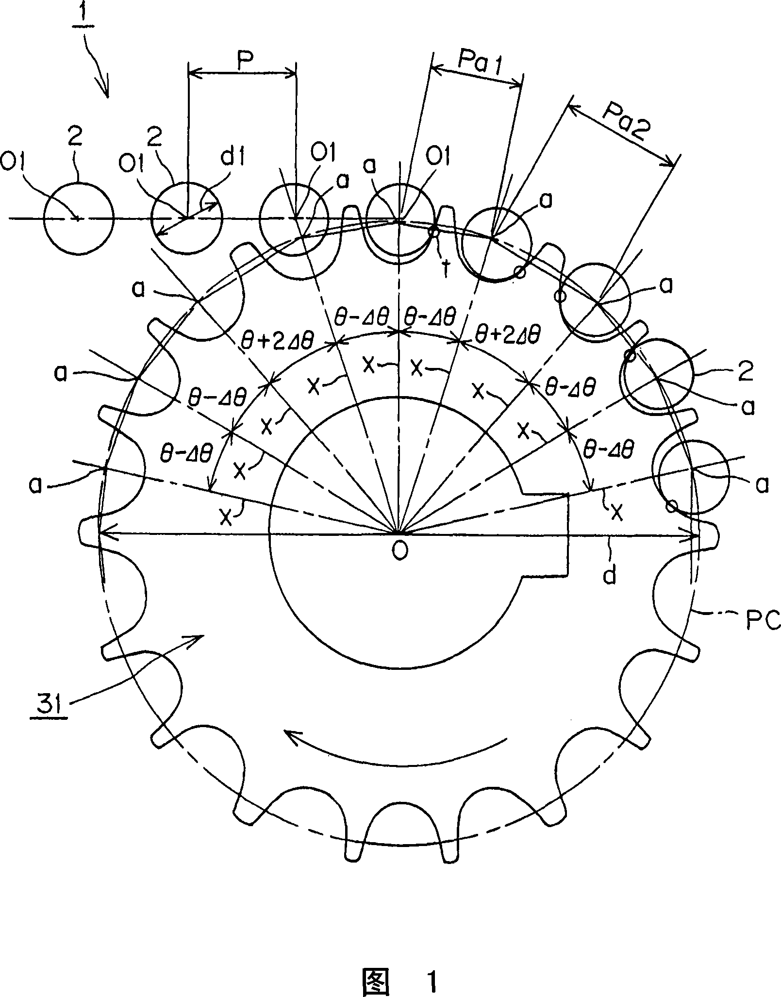
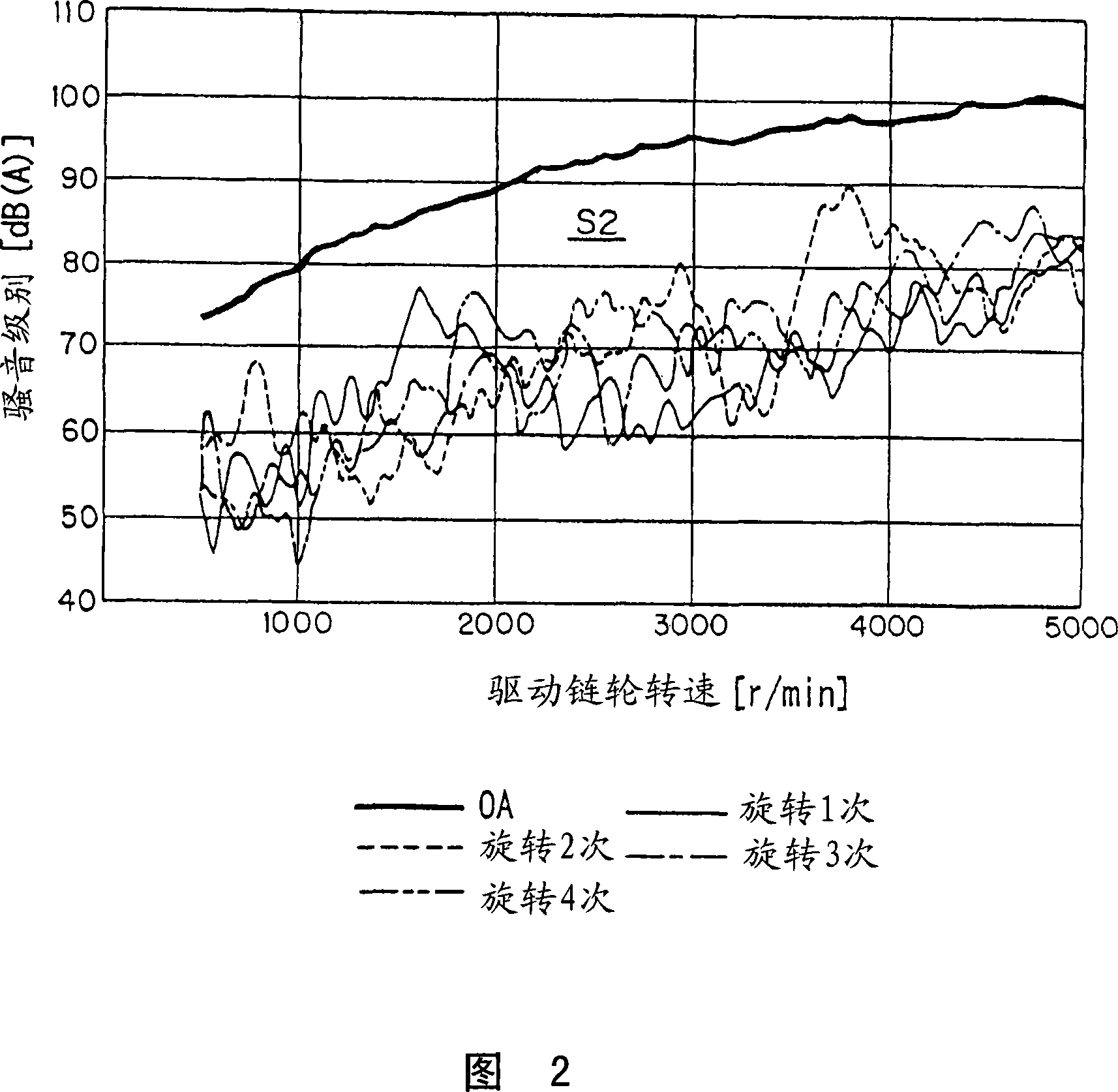
[0054] Next, the chain transmission device according to Embodiment 1 of the present invention will be described with reference to FIG. 1 and FIG. 2 . Fig. 1 is a front view showing a part of a meshing state of a standard roller chain and a sprocket of a chain transmission according to Embodiment 1 of the present invention. Fig. 2 is a graph showing the results of noise measurement of the chain transmission according to Example 1 of the present invention.

[0055] As shown in FIG. 1 , the chain transmission according to Embodiment 1 of the present invention includes a standard roller chain 1 and a sprocket 31 in which the rollers 2 of the standard roller chain 1 mesh with teeth.

[0056] As mentioned above, the standard roller chain 1 has: an inner chain link, the two ends of the two sleeves are respectively pressed into the sleeve holes of a pair of inner plates, and the roller 2 with an outer diameter of d1 is rotatably nested in the sleeve. On the outer circumference of the...

Embodiment 2

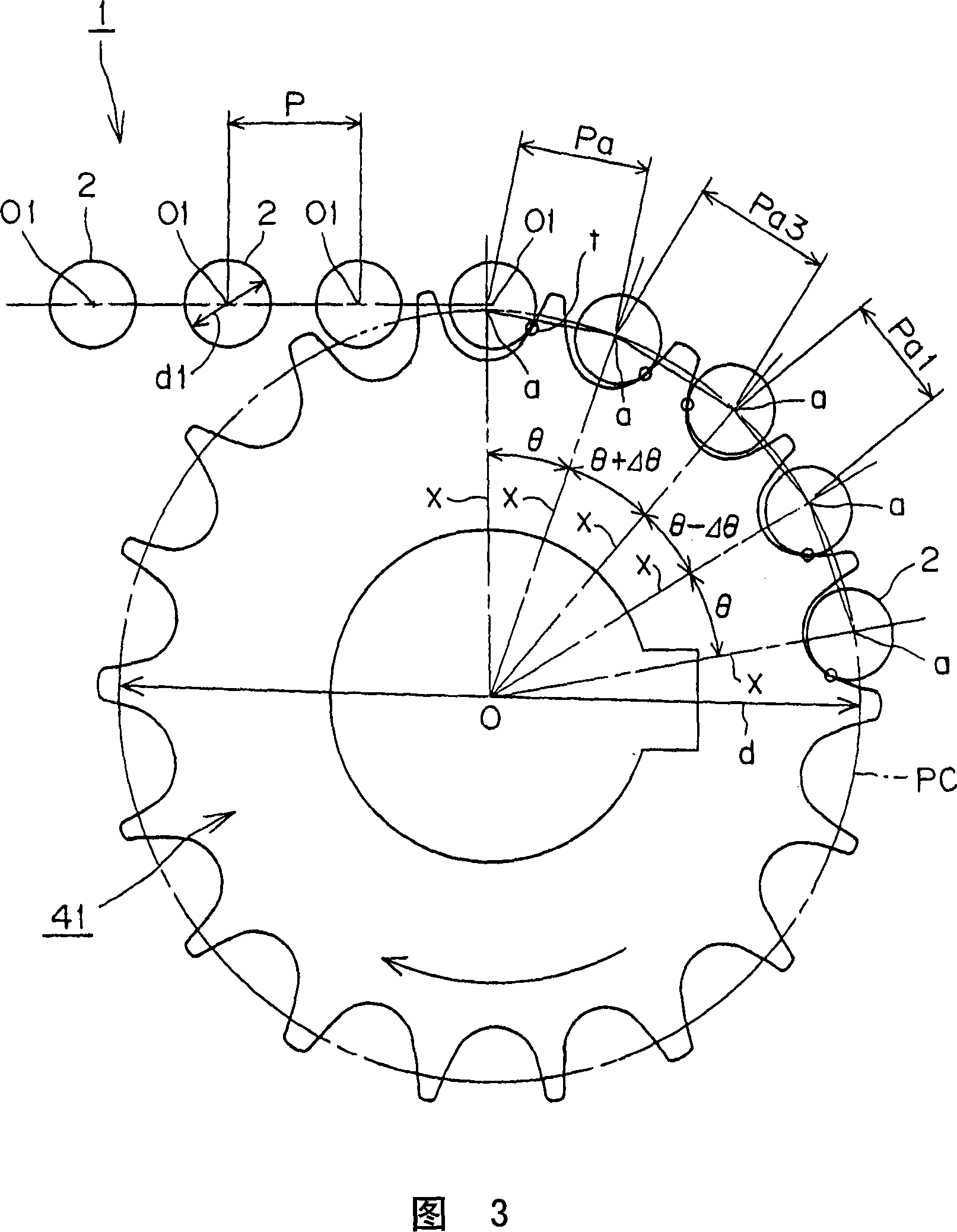
[0067] Next, a chain transmission device according to Embodiment 2 of the present invention will be described with reference to FIG. 3 . 3 is a front view showing a part of the meshing state of the standard roller chain and the sprockets of the chain transmission according to Embodiment 2 of the present invention.

[0068] As shown in FIG. 3 , the chain transmission according to Embodiment 2 of the present invention includes a standard roller chain 1 and a sprocket 41 in which the rollers 2 of the standard roller chain 1 mesh with teeth.

[0069] The standard roller chain 1 is as described in Embodiment 1 of the present invention, and thus its description is omitted.

[0070] The sprocket 41 differs only in that it has three different tooth pitch angles from the first embodiment of the present invention having two different pitches θ-Δθ and θ+2Δθ. As described above, for the convenience of the following description, the pitch angle θ of the teeth determined by the formula θ=3...


PUM


Abstract

In a roller or bushing chain transmission a standard roller or bushing chain having a uniform chain pitch meshes with a sprocket having at least two different tooth form pitches.

Description

technical field [0001] The present invention relates to a chain drive that reduces the noise generated when the rollers of a roller chain or the bushes of a bush chain mesh with the teeth of a sprocket. Background technique [0002] Conventionally, in the chain transmission device in which the rollers of the roller chain or the bushes of the bush chain mesh with the teeth of the sprocket, the roller chain for power transmission and the Bush chains and sprockets are more common. [0003] JIS B1801-1997 (roller chains and bush chains for transmission) is regulated in Japanese Industrial Standards (JIS), and the tooth shape of the sprocket (S-tooth profile, U profile and ISO profile). Attachment 2 (Shapes and Dimensions of Sprockets) of JIS B1801-1997 (Roller Chains and Bush Chains for Power Transmission) describes the following formulas. [0004] pa=p(1+(ds-d1) / d) [0005] In addition, in the above formula, pa is the tooth profile pitch (a-a for S tooth profile, e-e for U ...

Claims


Application Information

Patent Timeline
Patent Type & Authority Applications(China)
IPC IPC(8): F16H7/06F16H55/30
CPCF16H7/06F16H55/08F16H55/30
Inventor 佐仓俊儿平井晶园田胜敏
Owner TSUBAKIMOTO CHAIN CO
Features
  • R&D
  • Intellectual Property
  • Life Sciences
  • Materials
  • Tech Scout
  • Unparalleled Data Quality
  • Higher Quality Content
  • 60% Fewer Hallucinations
Learn More