Supercharge Your Innovation With Domain-Expert AI Agents!

Plasma display device

A technology of plasma display panels and display devices, which is applied to static indicators, cathode ray tube indicators, solid cathodes, etc., can solve the problems of rising manufacturing unit prices of driving parts, and achieve the effect of reducing manufacturing unit prices

Inactive Publication Date: 2008-01-16
LG ELECTRONICS(NANJING) PLASMA CO LTD
View PDF0 Cites 0 Cited by
  • Summary
  • Abstract
  • Description
  • Claims
  • Application Information

AI Technical Summary

Problems solved by technology

[0007] Therefore, in the conventional plasma display device, there is a problem that the manufacturing unit price increases due to the large number of driving parts.

Method used


Image

  • Plasma display device
  • Plasma display device
  • Plasma display device

Examples


Embodiment Construction

[0030] Hereinafter, the present invention will be described in conjunction with the accompanying drawings and specific embodiments.

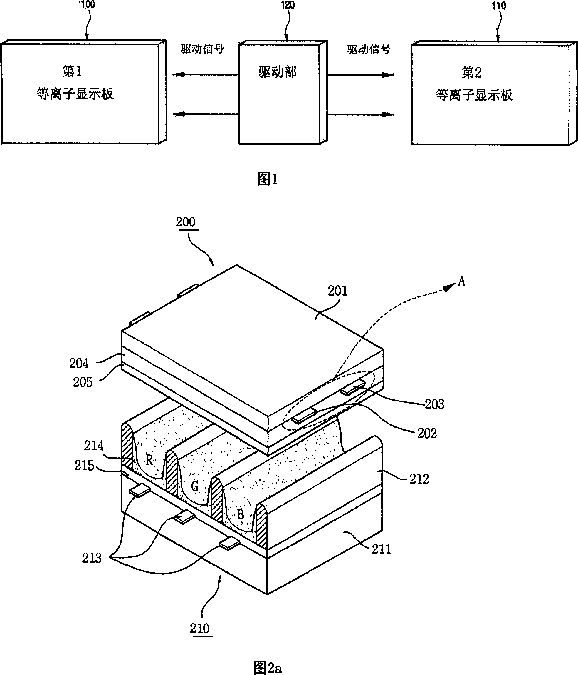
[0031] FIG. 1 is a schematic diagram illustrating the structure of a plasma display device of the present invention.

[0032] Analyzing FIG. 1 , the plasma display device of the present invention includes a plurality of plasma display panels, such as a first plasma display panel 100 , a second plasma display panel 110 and a drive unit 120 .

[0033] Driving unit 120 simultaneously applies a driving signal to electrodes formed on first plasma display panel 100 and electrodes formed on second plasma display panel 110 .

[0034] Here, FIG. 1 only shows an example in which the drive unit 120 is composed of one board (Board), but in the present invention, the drive unit 120 can adopt multiple boards according to the electrodes formed on the first and second plasma display panels 100 and 110. form.

[0035] For example, in the plasma display device ...


PUM


Abstract

The invention discloses a plasma display device, comrprise a first plasma panel containing electrode, a second plasma panel and a drive part for synchronously applying drive signal to the first plasma panel and second plasma panel. The said invention synchronously applies drive signal to the first plasma panel and second plasma panel by a drive part, therefore the making cost can be reduced.

Description

technical field [0001] The present invention relates to a plasma display device (Plasma Display Apparatus), in particular to a plasma display device that uses one drive unit to drive multiple plasma display panels. Background technique [0002] A plasma display device includes a plasma display panel on which electrodes are formed, and a drive unit that applies a certain drive signal to the electrodes of the plasma display panel. [0003] Usually, in a plasma display panel, a phosphor layer is formed in a discharge string (Cell) divided by barrier ribs, and a plurality of electrodes (Electrodes) are formed at the same time. [0004] Also, the driving unit applies a driving signal to the discharge strings through the electrodes. Then, a discharge is generated in the discharge string according to the provided driving signal. Wherein, when a discharge is generated in the discharge string by a driving signal, the discharge gas charged in the discharge string releases vacuum ult...

Claims


Application Information

Patent Timeline
Patent Type & Authority Applications(China)
IPC IPC(8): G09G3/28G09G3/296H01J11/22
CPCG09G3/294G09G3/296G09G5/14G09G2310/0205H01J11/34H01J17/492
Inventor 安星泰
Owner LG ELECTRONICS(NANJING) PLASMA CO LTD
Features
  • R&D
  • Intellectual Property
  • Life Sciences
  • Materials
  • Tech Scout
  • Unparalleled Data Quality
  • Higher Quality Content
  • 60% Fewer Hallucinations
Learn More