
Roller unit having traveling and guide function and pallet transport system using the same

A guiding function and guiding roller technology, applied in the direction of conveyors, electrical components, conveyor objects, etc., can solve the problems of foreign matter, pallet 10 shaking left and right, noise, etc., to save manufacturing unit price, smooth pallet movement, and improve durability sexual effect

Pending Publication Date: 2021-02-02
BNS株式会社 +1
View PDF3 Cites 0 Cited by
  • Summary
  • Abstract
  • Description
  • Claims
  • Application Information

AI Technical Summary

Problems solved by technology

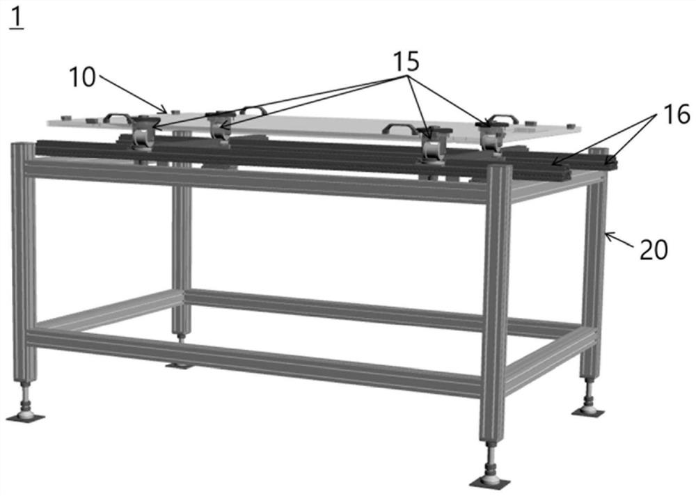
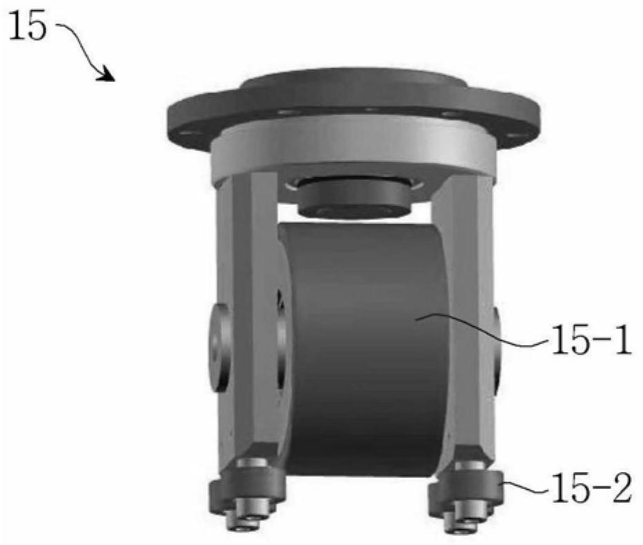
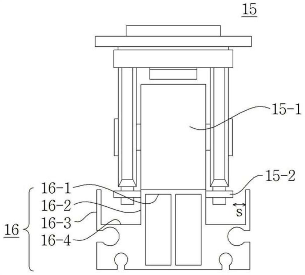
[0011] But as far as the prior art is concerned, the guide wheel 15-2 of the roller unit 15 is configured between the side wall surface 16-2 of the running track 16 and the track partition wall 16-3. There are still problems of vibration and noise caused by shaking from side to side at a distance S
[0012] That is, when the roller unit 15 of the prior art is attached and travels, a separation distance S occurs due to the gap between the guide wheel 15-2 of the roller unit 15 and the running rail, not only in the gap space foreign substances, and the tray 10 itself shakes from side to side, causing noise due to vibration. In addition, when inspection is carried out with the help of specific inspection equipment during transfer, a separation process occurs in which the entire tray 10 is lifted to the upper part and then lowered. situation, there are problems such as interference between the roller unit 15 and the running track 16

Method used


Image

  • Roller unit having traveling and guide function and pallet transport system using the same
  • Roller unit having traveling and guide function and pallet transport system using the same
  • Roller unit having traveling and guide function and pallet transport system using the same

Examples


Embodiment Construction

[0094] The preferred embodiments of the present invention will be described in detail below with reference to the accompanying drawings. The relevant descriptions of the present invention are only examples for structural and functional descriptions, so the scope of rights of the present invention should not be construed as being limited by the embodiments described below. That is, the embodiment can be changed in various ways and can have various forms, and therefore, the scope of the right of the present invention should be understood to include equivalents that can realize the technical idea.

[0095]On the other hand, the meanings of the terms described in the present invention should be understood as follows. Terms such as "first" and "second" are used to distinguish one constituent element from other constituent elements, and the scope of rights shall not be limited by these terms. For example, a first constituent element may be named a second constituent element, and sim...


PUM


Abstract

The present invention relates to a roller unit including a driving function and a guide function. The roller unit including the driving function and the guide function and coupled to a pallet for transferring a substrate includes a guide roller attached to be inclined to a horizontal surface, so that the guide roller can be prevented from a deviation from a driving rail and can be stably driven while being on the driving rail having an inclined cross section. The roller unit including the driving function and the guide function and coupled to the pallet for transferring a substrate comprises:a rotation unit installed on a base of the pallet to be to rotatable; a caster block having the cross section inclined toward the lower side on the left and right, and coupled to the rotation unit bya coupling member; and multiple guide rollers connected to the inclined cross section on the left and the right of the caster block. Therefore, according to the present invention, the roller unit including the driving function and the guide function can be stably driven by using a structure including both the driving function and the guide function, and can be prevented from a deviating from the driving rail at the same time.

Description

technical field [0001] The present invention relates to a roller unit having traveling and guiding functions in a pallet transfer system and a pallet transferring system using the same, and more particularly, to a roller unit having traveling and guiding functions and a pallet transferring system utilizing the same. The roller units are connected to each other. In the tray used for substrate transfer between processes, the roller unit is provided with guide rollers attached obliquely with respect to the horizontal plane, and the guide rollers are prevented from detaching from the traveling track while traveling along the traveling track having the inclined end surface, enabling stable traveling. Background technique [0002] Generally, diffusion, etching, photolithography, cleaning processes, and the like are performed in order to manufacture a semiconductor element. This process should be connected with the previous process, and after each process is completed, it will be t...

Claims


Application Information

Patent Timeline
IPC IPC(8): H01L21/677
CPCH01L21/67703H01L21/6773H01L21/67706H01L21/67259H01L21/68764B65G49/061B65G2201/022
Inventor 吴珖根河在福
Owner BNS株式会社
Learn More