Mover for linear motor and manufacturing method thereof, linear motor comprising motor

The technology of a linear motor and manufacturing method is applied in the direction of electric components, motor generators, electrical components, etc., which can solve the problems of complex manufacturing process, enlarged size, and increased size and weight of the mover 12, so as to reduce the manufacturing unit price, The effect of improving manufacturing yield and reducing overall size and weight

Inactive Publication Date: 2013-09-11
MIRAE CORPORATION
View PDF7 Cites 0 Cited by
  • Summary
  • Abstract
  • Description
  • Claims
  • Application Information

AI Technical Summary

Problems solved by technology

Therefore, the manufacturing process of the linear motor 10 related to the prior art is complicated, and there is a problem that the manufacturing process takes a considerable amount of time.
Since two coils 122 are combined on each coupling part 121 of the linear motor 10 involved in the prior art, the above-mentioned problems are further serious.
[0011] Third, in the linear motor 10 related to the prior art, there is a problem that the above-mentioned coupling member 1211 causes the size of the above-mentioned coupling member 121 to become larger, and thus, there is a problem that the size and weight of the above-mentioned mover 12 are increased.

Method used


Image

  • Mover for linear motor and manufacturing method thereof, linear motor comprising motor
  • Mover for linear motor and manufacturing method thereof, linear motor comprising motor
  • Mover for linear motor and manufacturing method thereof, linear motor comprising motor

Examples


Embodiment Construction

[0027] Next, preferred embodiments of the mover for a linear motor according to the present invention will be described in detail with reference to the drawings.

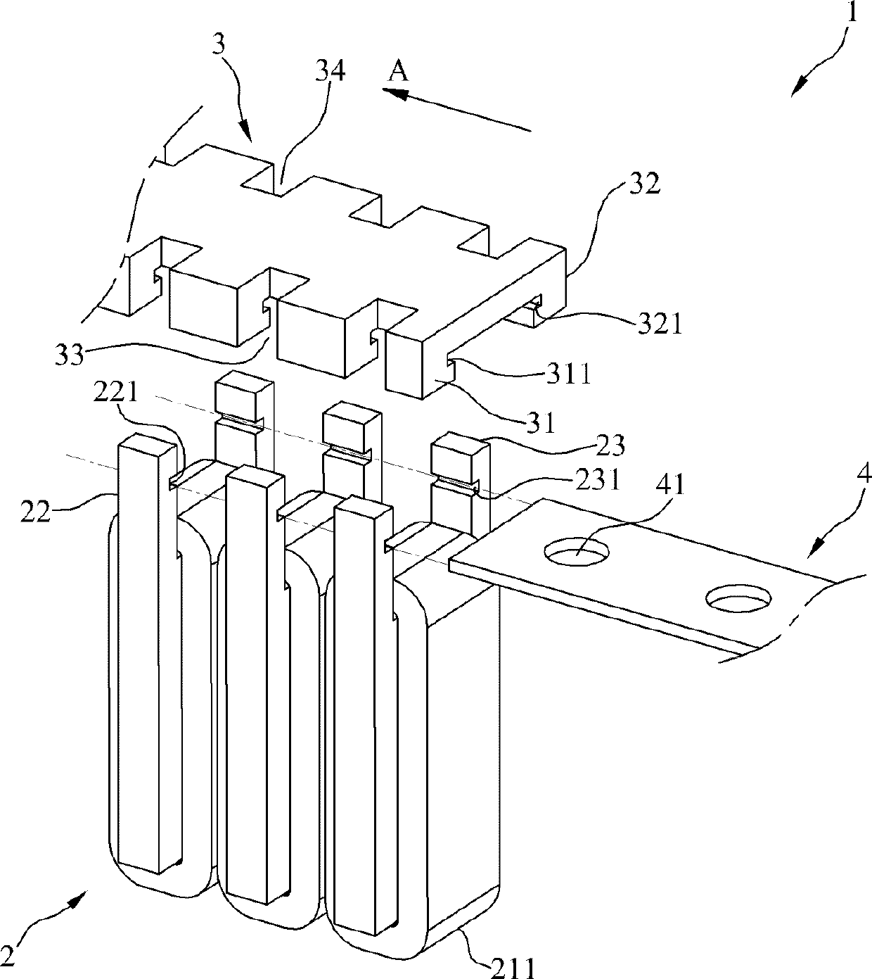
[0028] image 3 It is an exploded perspective view schematically showing a mover for a linear motor according to the present invention; Figure 4 It is a perspective view schematically showing the assembled state of the mover for a linear motor according to the present invention; Figure 5 is a perspective view schematically showing a coil component according to the present invention; Figure 6 It is a conceptual diagram schematically showing a combination relationship of movers for linear motors according to the present invention; Figure 7 It is a side view showing the coupled state of the mover for a linear motor according to the present invention.

[0029] refer to image 3 , The mover 1 for a linear motor according to the present invention includes a coil component 2 , a connection component 3 and a couplin...


PUM


Abstract

The invention provides a mover for a linear motor and a manufacturing method thereof, and a linear motor comprising the motor. The mover for a linear motor of the invention comprises: a connecting component which comprises a first protruding component provided with a first combining slot and a second protruding component provided with a second combining slot; a coil component which comprises a coil main body combined with the coil, a first combined main body provided with a first inserting slot, and a second combined main body provided with a second inserting slot; and a combining component with one side inserted into the first combining slot and the first inserting slot and the other side inserted into the second combining slot and the second inserting slot, so the coil component is combined with the connecting component. The invention can reduce manufacturing unit cost, increase manufacturing yield, and decrease overall dimensions and weight.

Description

technical field [0001] The present invention relates to a linear motor that moves a mover by using thrust generated between a mover (Mover) and a stator (Stator). Background technique [0002] Linear motors are driving devices that move objects linearly. Compared with existing linear motion devices that use ball screws, chains, and belts, etc., they are simple in structure, small in installation area, and excellent in moving speed and thrust, so they are used in various industries. field. For example, it is applied to testing machines such as test handlers (Test Handler) and the field of sorting technology, and the field of surface mount technology (Surface Mount Technology) such as surface mounters. [0003] figure 1 It is a perspective view schematically showing a mover of a linear motor related to the prior art; figure 2 It is a sectional view schematically showing a conventional linear motor. [0004] refer to figure 1 as well as figure 2 , the linear motor 10 in...

Claims


Application Information

Patent Timeline
Patent Type & Authority Patents(China)
IPC IPC(8): H02K41/02H02K41/03H02K15/08H02K15/12
CPCH02K15/03H02K41/031
Inventor 金舜镐申俊浩
Owner MIRAE CORPORATION
Why Eureka
Try Eureka