Display quality automatic regulation device and method based on environment induction

A technology for automatic adjustment of device and display quality, applied to lighting devices, static indicators, cathode ray tube indicators, etc. Influence of visual effects, good display quality, effect of balancing visual effects and environmental protection requirements

Inactive Publication Date: 2008-01-16
温建荣
View PDF0 Cites 15 Cited by
  • Summary
  • Abstract
  • Description
  • Claims
  • Application Information

AI Technical Summary

Problems solved by technology

[0050] Obviously, if the LED display maintains a fixed brightness, the parameters suitable for LED display in a bright environment (such as brightness, contrast, gamma coefficient, etc.) are applied to the LED display in a low-brightness environment, which will bring visual impacts such as excessive brightness and contrast ; In this way, the visual effect is reduced, causing visual pollution and energy waste
On the contrary, applying the parameters suitable for LED display in dark environments (such as brightness, contrast, gamma coefficient, etc.) to LED display in low-brightness environments will bring about visual effects such as insufficient brightness and decreased contrast; this will lead to insufficient brightness , can not meet the display requirements, affecting system performance
[0051] Furthermore, if the parameters suitable for LED display in a high-transparency environment (such as brightness, contrast, etc.) are applied to an LED display in a low-transparency environment, it will bring about visually reduced brightness, grayscale, and viewing distance, etc., which will affect system performance.
On the contrary, applying the parameters (such as brightness, contrast, etc.) suitable for LED display in a low-transparency environment to LED display in a low-transparency environment will bring about visual effects such as high brightness and high contrast; this will reduce the visual effect and cause visual pollution. Also wastes energy
[0052] From the above analysis, it can be known that environmental factors and environmental parameters will significantly affect the visual effect of the LED display system through environmental factors, but the traditional LED display system cannot effectively overcome these effects, thus showing poor visual effects

Method used


Image

  • Display quality automatic regulation device and method based on environment induction
  • Display quality automatic regulation device and method based on environment induction
  • Display quality automatic regulation device and method based on environment induction

Examples


Embodiment Construction

[0086] The present invention will be described in detail below with reference to the accompanying drawings and in combination with embodiments.

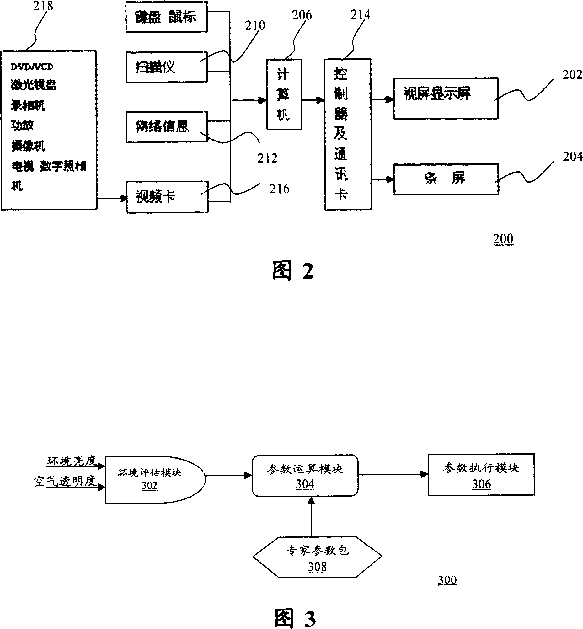
[0087] FIG. 3 shows a device for automatically adjusting display quality based on environment sensing according to the present invention.

[0088] As shown in FIG. 3 , the display quality automatic adjustment device 300 based on environment sensing according to the present invention includes:

[0089] Environmental evaluation module 302, which senses the optical conditions of the outside world (for example, ambient brightness or air transparency) to obtain the sensing value, and then transmits it to the parameter operation module 304 as a basis for calculation;

[0090] A parameter operation module 304, which performs operations on the sensing value to obtain adjustment parameters (for example, adjustment brightness, gamma coefficient), and then transmits it to the parameter execution module 306; and

[0091] The parameter execution...


PUM


Abstract

The invention provides a method for adjusting display quality automatically on the basis of optical condition, and includes the following steps: (a). sense the external optical condition to obtain the sensing value; (b). calculate the sensing value to obtain the adjustment parameter; (c). display the system's working parameter (brightness and gamma coefficient) through the adjustment parameters so as to procure better display quality (visual brightness, grayness, and visual distance). The invention also provides a device for adjusting display quality automatically.

Description

technical field [0001] The present invention relates to the display field, and more specifically, to an environment sensing-based automatic display quality adjustment device and method, especially an environment sensing-based LED display quality automatic adjustment device and method. Background technique [0002] In the PN junction of some semiconductor materials, when the injected minority carriers recombine with the majority carriers, the excess energy will be released in the form of light, thereby directly converting electrical energy into light energy. When a reverse voltage is applied to the PN junction, it is difficult for minority carriers to inject, so it does not emit light. This kind of diode made by the principle of injection electroluminescence is called light emitting diode, referred to as LED (Light Emitting Diode) [0003] The luminous color and luminous efficiency of LED are related to the material and process of making LED. At present, red, green and blue ...

Claims


Application Information

Patent Timeline
IPC IPC(8): G09G3/32G09G3/30G09G3/20G09G5/10G09G5/02G09G5/00H05B33/08H05B33/14H05B44/00
Inventor 青发富
Owner 温建荣
Why Eureka
Try Eureka