Enhanced plasma light-emitting signal collector

A technology of plasma and luminescent signals, which is applied in the direction of material excitation analysis, etc., to achieve the effect of extending distance, reducing optical pollution and prolonging the life of optical fiber

Inactive Publication Date: 2015-10-07
CHINA INSTITUTE OF ATOMIC ENERGY
View PDF9 Cites 4 Cited by
  • Summary
  • Abstract
  • Description
  • Claims
  • Application Information

AI Technical Summary

Problems solved by technology

Adding reflectors composed of ellipses and hemispheres to LIBS to increase the collection solid angle The author has not found in the literature and patents

Method used


Image

  • Enhanced plasma light-emitting signal collector
  • Enhanced plasma light-emitting signal collector
  • Enhanced plasma light-emitting signal collector

Examples


Embodiment Construction

[0021] The present invention will be described in detail below with reference to the accompanying drawings and embodiments.

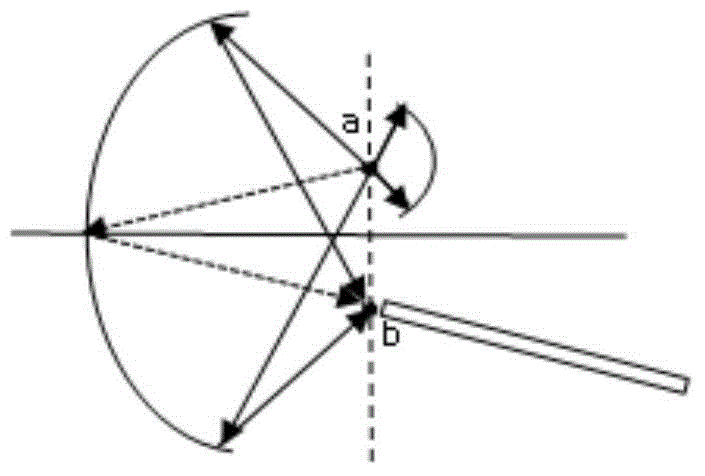
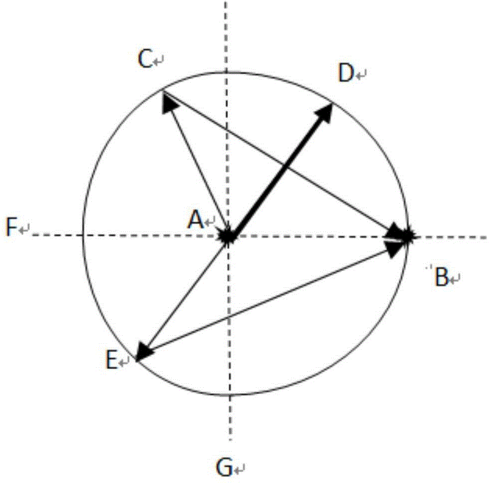
[0022] like figure 2 As shown, it is a sectional view of a collection device designed by the present invention, including an ellipsoid reflector and a hemispherical reflector, and the opening edge of the ellipsoid reflector and the opening edge of the hemispherical reflector are matched to form a closed Collection optical cavity. The curve on the left of the dotted line G is an ellipse, the right side is a semicircle, the dotted line F is the straight line where the long axis of the ellipse is located, points A and B are the two foci of the left ellipse, and point A is the center of the right semicircle, and point B is the right semicircle vertices. Point A is the light-emitting point. The light emitted from point A to the left is focused by the ellipsoid mirror to another focus point B (ie A-C-B), while the light emitted from point A to the right ha...


PUM


Abstract

The invention relates to an enhanced plasma light-emitting signal collector. The collector comprises an elliptical reflector and a half spherical reflector. The drift diameter of the ellipsoid is equal to the diameter of the sphere. The radius of the sphere is equal to the distance between two focuses of the ellipsoid. The edge of an opening of the elliptical reflector is matched with the edge of an opening of the half spherical reflector so as to form a sealed light collecting cavity. The connecting line of the ellipsoid and the sphere is perpendicular to a long axis of the ellipsoid. The collector can enlarge the collecting solid angle, greatly improve optical collecting efficiency, optimize the collected light spots, enlarge the distance between the plasma light-emitting points and collecting optical fiber probes and reduce optical pollution of the surfaces of the probes, and the service life of optical fiber is prolonged. The sealed light collecting cavity is isolated from the external environment, and the environment where LIPS triggering points can be controlled.

Description

technical field [0001] The invention particularly relates to an enhanced plasma luminescence signal collector, which belongs to the field of optical signal receivers. Background technique [0002] LIPS technology is the abbreviation of Laser Induced Plasma Spectroscopy, also known as Laser Induced Breakdown Spectroscopy (LIBS) or Laser Excitation Spectroscopy (LSS). During the plasma cooling process, the electron energy level transitions to emit characteristic spectrum, and the elements contained in the sample can be qualitatively and quantitatively analyzed by analyzing the characteristic spectrum. LIPS is not limited by the appearance of the sample, and can detect a variety of samples in solid, liquid, and aerosol forms. In addition, LIPS technology has the advantages of high detection limit (up to ppb level), fast measurement speed (less than one second), and remote non-contact measurement. [0003] The key point of LIBS technology is to improve the obtained signal inte...

Claims


Application Information

Patent Timeline
Patent Type & Authority Applications(China)
IPC IPC(8): G01N21/63
Inventor 韩丽璇高智星汤秀章
Owner CHINA INSTITUTE OF ATOMIC ENERGY
Why Eureka
Try Eureka