

Flat form battery
A flat-shaped battery technology, applied to battery components, circuits, electrical components, etc., can solve the problems that external equipment and batteries cannot be connected, external equipment cannot be installed, and the external size of batteries increases, so as to reduce material costs , to prevent the corresponding reduction, to suppress the effect of external dimensions
- Summary
- Abstract
- Description
- Claims
- Application Information
AI Technical Summary
Problems solved by technology
Method used
Image

Examples
Embodiment Construction
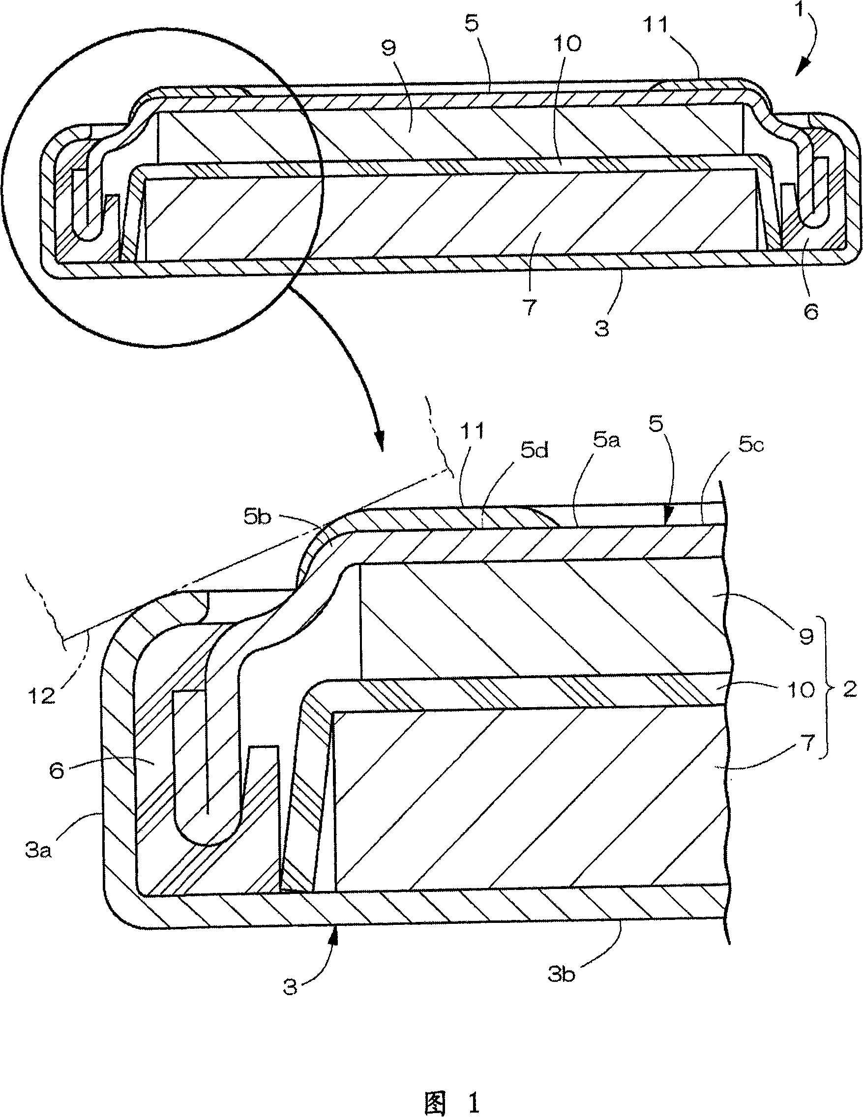
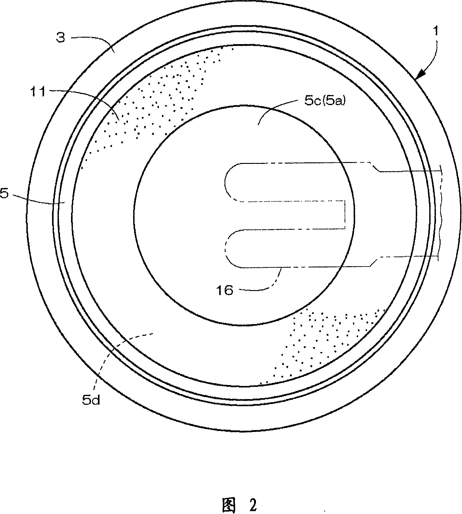
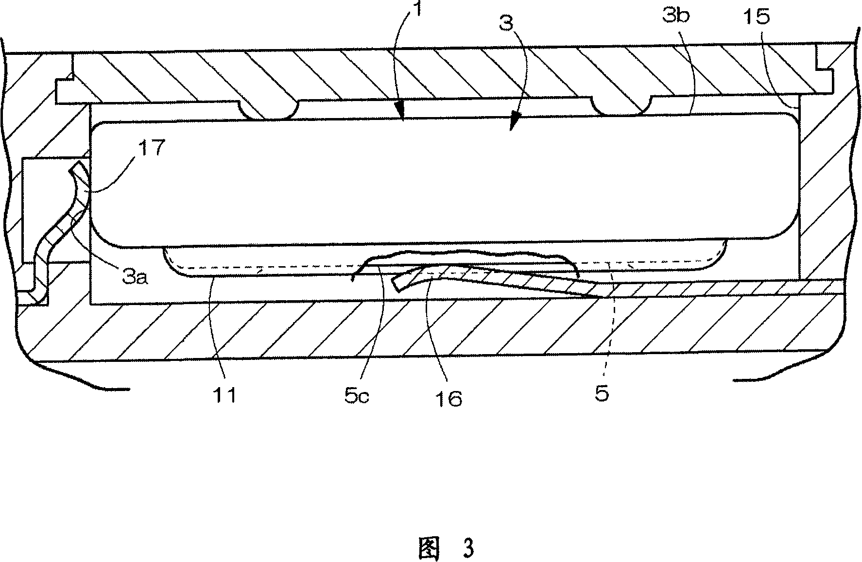
[0029] The drawings show an example of a primary battery which is a flat battery which is the object of the present invention. As shown in FIG. 1 , the battery container 1 is composed of an upwardly opening shallow dish-shaped positive electrode case (outer case) 3 and a downwardly opening shallow dish-shaped negative electrode case (sealing cover) 5, and the whole is made into a flat coin shape. The nominal voltage of the above-mentioned flat battery is 3V. Inside the battery container 1 , the power generating element 2 is accommodated, and an annular gasket 6 is arranged between the positive electrode case 3 and the negative electrode case 5 .
[0030] And, under the state that the power generation element 2 is accommodated inside the positive pole case 3, the negative pole case 5 is inserted into the opening inner edge side of the positive pole case 3 via the gasket 6, and fixed by riveting (the state of FIG. 6 The battery container 1 is sealed between the positive electro...
PUM
 Abstract
Description
Claims
Application Information