
Method and device for providing synchronous rectification circuit of off-line power converter

一种功率转换器、同步整流的技术,应用在有中间变换为交流的变换设备、输出功率的转换装置、交流功率输入变换为直流功率输出等方向,能够解决额外功率消耗等问题

Inactive Publication Date: 2008-01-16
SYST GEN
View PDF1 Cites 30 Cited by
  • Summary
  • Abstract
  • Description
  • Claims
  • Application Information

AI Technical Summary

Problems solved by technology

However, the disadvantage of this prior art is the extra power consumption caused by the saturable inductor and / or the current sensing device

Method used


Image

  • Method and device for providing synchronous rectification circuit of off-line power converter
  • Method and device for providing synchronous rectification circuit of off-line power converter
  • Method and device for providing synchronous rectification circuit of off-line power converter

Examples


Embodiment Construction

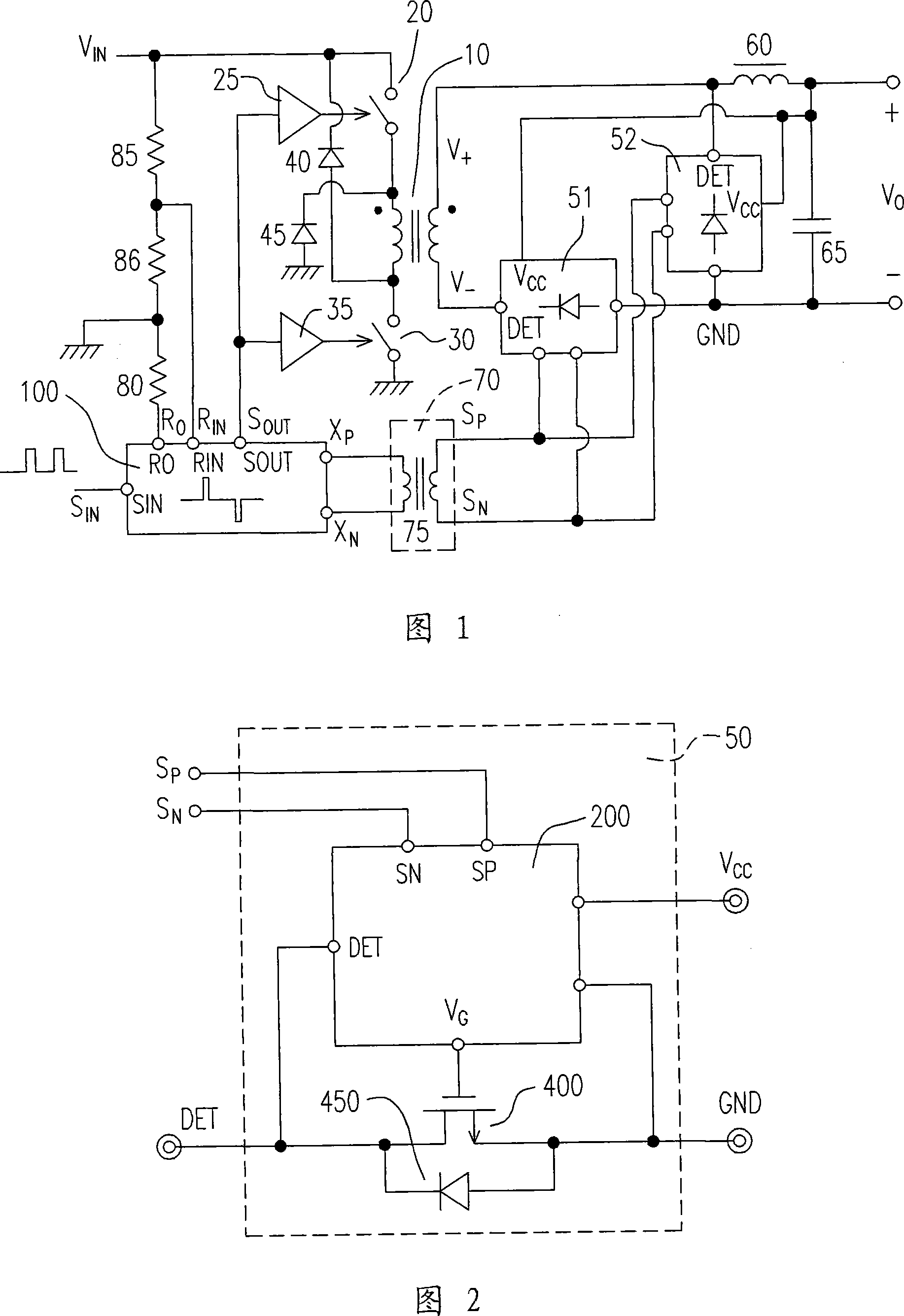
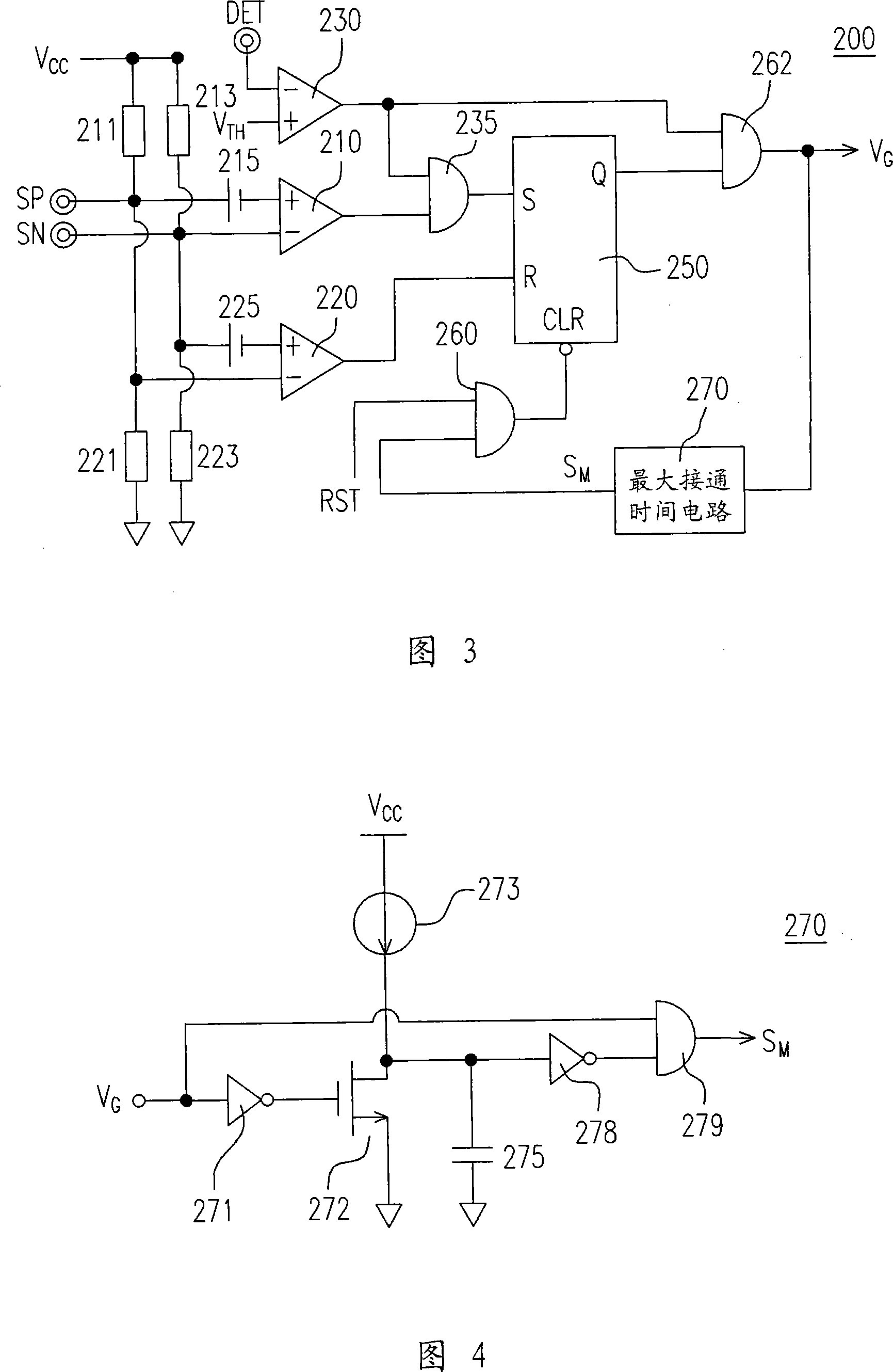
[0016] Fig. 1 shows a power converter with a synchronous rectifier according to an embodiment of the invention. The power converter comprises a transformer 10 having a primary side and a secondary side. The primary side of the transformer 10 has two power switches 20 and 30 for switching the transformer 10 . The secondary side of the transformer 10 includes a first terminal V+ and a second terminal V−. According to the switching of the transformer 10, a switching voltage is generated across the second terminal V− and the first terminal V+. The first synchronous rectifier 51 has a rectification terminal DET connected to said second terminal V-. The ground terminal GND of the first synchronous rectifier 51 is connected to the ground of the power converter. The second synchronous rectifier 52 is connected from the first terminal V+ to the ground of the power converter. The inductor 60 is connected from the first terminal V+ to the output V of the power converter O . The fir...


PUM


Abstract

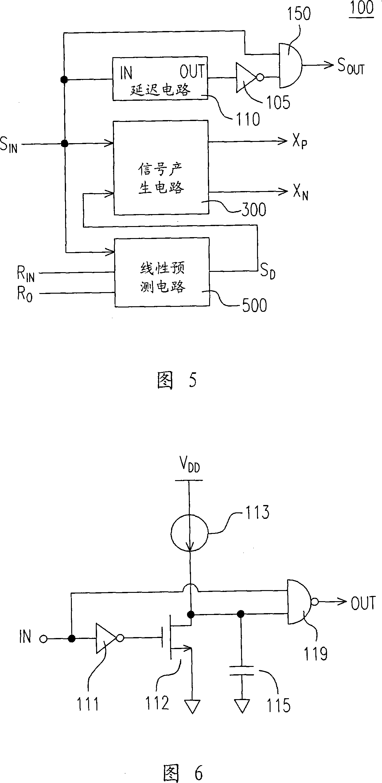
The invention provides a synchronous rectifier circuit for the power converter. An impulse signal generating device answers for the front edge and the back edge of the switch signal to generate the impulse signal. The switch signal is used to switch the transformer of the power converter, for instance, an isolation apparatus of the impulse transformer or mini capacitor couple to the impulse signal generating device to transfer the isolation barrier of the impulse signal passing through the transformer. The synchronous rectifier comprises a power switch and a control circuit. The power switch is arranged between the secondary side of the transformer and the output of the power transformer for the rectification. The control circuit having the bolt lock device receives the impulse signal to turn-off the power switch.

Description

technical field [0001] The present invention generally relates to a control circuit for a power converter, and more particularly, to a synchronous rectification control circuit for a power converter. Background technique [0002] The off-line power converter includes a power transformer. For safety reasons, the power converter provides isolation between the AC input and the output of the power converter. In recent research and development, the application of synchronous rectifiers in the secondary side of transformers is to achieve high-efficiency conversion of power converters, such as Yang's No. 7,173,835 entitled "Control circuit associated with saturated inductor operated assynchronous rectifier forward power converter" US patent. However, the disadvantage of this prior art is the extra power consumption caused by the saturable inductor and / or the current sensing device. Saturable inductors and current sensing devices are required to aid in the operation of the synchro...

Claims


Application Information

Patent Timeline
Patent Type & Authority Applications(China)
IPC IPC(8): H02M7/12H02M7/217H02M3/28H02M3/335
CPCH02M1/08H03K17/80H03K17/74H03K17/28
Inventor 杨大勇陈佐民
Owner SYST GEN
Learn More