Chain tightening device

A chain tensioner and rack technology, applied in hand-held tools, manufacturing tools, etc., can solve problems such as low efficiency, low strength, and insufficient load-bearing capacity, so as to reduce intermediate links, strong load-bearing capacity, and work high efficiency effect

Active Publication Date: 2008-01-23
CHANGZHI YUANLU MINING EQUIP
View PDF1 Cites 14 Cited by
  • Summary
  • Abstract
  • Description
  • Claims
  • Application Information

AI Technical Summary

Problems solved by technology

The chain tensioner needs to pass multiple force transmissions to achieve the purpose of the retractable hook, so the efficiency is low
At the same time, s

Method used


Image

  • Chain tightening device
  • Chain tightening device

Examples


Embodiment Construction

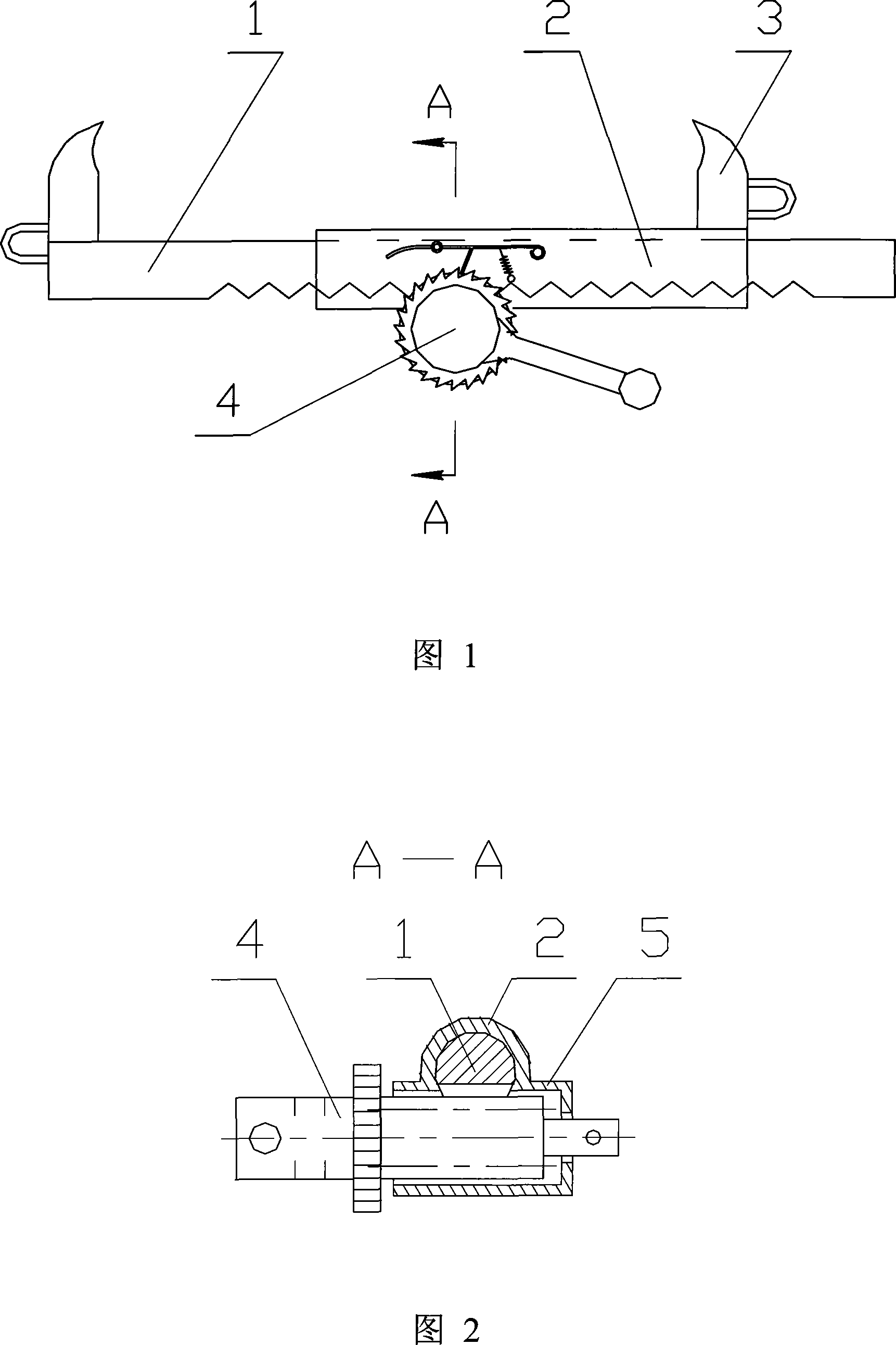
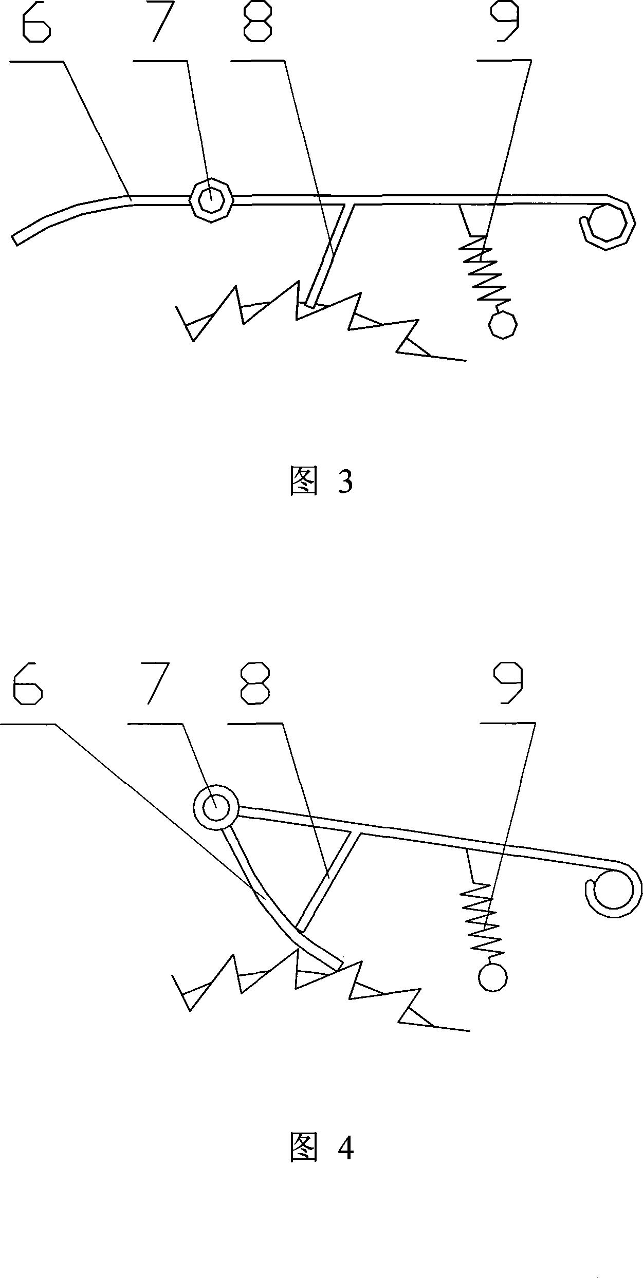
[0013] Shown in Fig. 1 and Fig. 2, the present invention is made up of drag hook 3, force application device, rack 1, pinion, pinion sleeve and non-return mechanism. The rack 1 is installed in the rack sleeve 2, and is slidably matched with the rack sleeve 2. Two drag hooks 3 are respectively welded on the rack 1 and the rack cover 2, and can also be fixed on the rack 1 and the rack cover 2 with bolts. The lower part of the rack sleeve 2 is welded or screwed to the sleeve 5, and the upper part of the sleeve 5 is vertically connected with the lower part of the rack sleeve 2, so that the force applying device is located in the sleeve 5 and fits with the sleeve 5 in a gap. The gear shaft meshes with the exposed rack 1 through the through hole of the freewheel part. The force applying device is made up of rotating shaft 4 and non-return mechanism. One end of the rotating shaft 4 is welded with a rotating handle, and the middle part has a toothed disc, which can be fixed on the r...


PUM


Abstract

The invention discloses a chain tightener of high efficiency and strong bearing and loading capability, which comprises a drag hook and a force application device, a gear strip is positioned in the gear strip sleeve, the drag hook is arranged on the gear strip and the gear sleeve, a sleeve is arranged under the gear strip sleeve, the upper part of the sleeve and the lower part of the gear strip sleeve are communicated vertically; the force application device is positioned in the sleeve, the gear axle of the force application device is hinged with the gear strip. The force application device is composed of a rotating axle and a non-return structure, one end of the rotating axle is arranged with a rotating handle and a gear plate is arranged in middle, a gear axle is arranged corresponding to the gear strip, the other end of the rotating axle is a step axle, a pin hole is arranged on the step axle penetrating through the bottom hole of the sleeve, a pin is arranged in the pin hole. The no-return structure is composed of a gear plate and the flexible braking structure. The flexible braking structure is composed of a spring, a gear pole and a hinge shaft, the two ends of the spring are fixed on the gear strip sleeve shell and the gear pole respectively, one end of the gear pole is fixed on the gear strip sleeve shell, the other end is hang in the air and provided with a hinge shaft, a top gear is arranged in the middle, the fold plate and the gear pole are hinged. The invention is used for chain tight of scraper conveyor.

Description

technical field [0001] The invention relates to a chain tensioner of a mine scraper conveyor. Background technique [0002] Many coal mines now use scraper conveyors, and it is often necessary to lengthen or shorten the chain links of scraper conveyors. The traditional method is to rely on manual operations. Reverse to achieve the purpose of removing the chain. However, the way of jogging the motor is easy to cause damage to the equipment, and it is a relatively dangerous operation. Frequently, the chain link is still strong and the worker's fingers are squeezed, and in severe cases, the fingers are broken. Although this method of operation is relatively fast, it is not allowed in the operating regulations of the coal mine, and it is an illegal operation. But it is very inconvenient to use 5 tons of guide chains to disassemble according to existing operating procedures. The Chinese patent No. 200520073289.6 discloses a scraper transport chain tensioner, which basically so...

Claims


Application Information

Patent Timeline
IPC IPC(8): B25B27/22
Inventor 王跃平李彬
Owner CHANGZHI YUANLU MINING EQUIP
Why Eureka
Try Eureka