
Automatic control device of tire pressure

An automatic control device and tire pressure technology, applied in tire measurement, tire parts, transportation and packaging, etc., can solve problems such as tire blowout, increased fuel consumption, abnormal hot tires, etc., to prevent traffic accidents, prolong service life, The effect of saving fuel consumption

Inactive Publication Date: 2008-01-23
曾干
View PDF0 Cites 17 Cited by
  • Summary
  • Abstract
  • Description
  • Claims
  • Application Information

AI Technical Summary

Problems solved by technology

If the air pressure in the tire is too high, it is easy to burst; if the air pressure is insufficient, the frictional resistance between the tire and the ground will increase, driving will be difficult, fuel consumption will increase, and abnormal hot tires will occur. After a long time, the tire will easily burst
[0003] Although tubeless tires have many advantages, they are: 1. The production materials are tight and the technical requirements are strict; 2. The tire edge and high pressure sealing requirements are high; 3. Special equipment is required for inflating; 4. It is not easy to repair if it is broken; 5. Naturally deflated The rate is much higher than other types of tires, so tubeless tires are also threatened by too high or too low pressure in the tire
[0004] The recently appeared intelligent wireless tire pressure monitoring system can monitor tire pressure and tire temperature, but the design value of tire pressure cannot be maintained. It can only detect problems, but cannot prevent the occurrence of excessive or low pressure in the tire. What's more, the wireless tire pressure monitoring system is an electronic product, which has poor anti-fouling, anti-corrosion, moisture-proof and shock-proof performance. Of course, the reliability will change accordingly after a long time of use.

Method used


Image

  • Automatic control device of tire pressure
  • Automatic control device of tire pressure
  • Automatic control device of tire pressure

Examples


Embodiment Construction

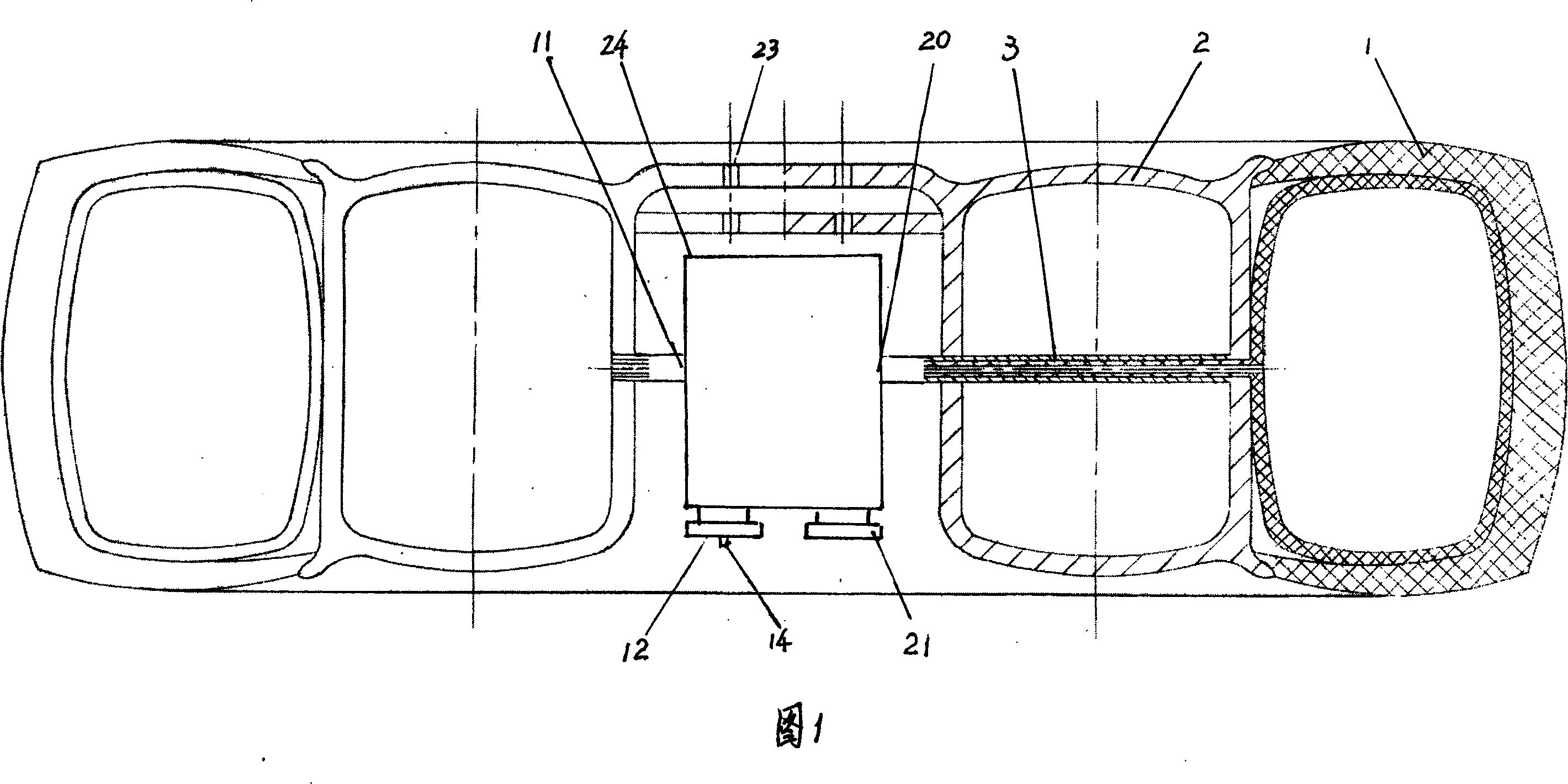
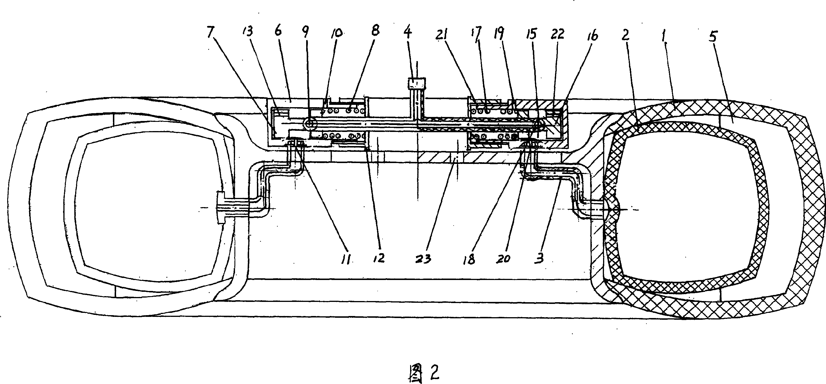
[0019] In Fig. 1, namely embodiment 1: the tire 1 is a tire with an inner tube, the high-pressure air bag 2 is close to the inner circle of the tire 1, and is fixed on the side of the tire 1, and the high-pressure valve and the low-pressure valve are a parallel integrated valve body, fixed At the center of the high-pressure air bag 2, the tire main shaft coupling port 23 is connected with the wheel main shaft.

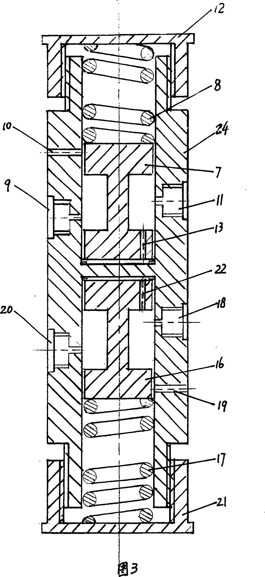
[0020] In Fig. 4, the left side is a high-pressure valve, the right side is a low-pressure valve, there are air inlet 9, exhaust hole 10 and Unicom hole 11 on the left side of the valve body 24, and the air inlet 9 passes through the pipeline and the right low-pressure valve. Connected, and connected with the intake pipe 4, the exhaust hole 10 is connected with the atmosphere, a whistle is installed in the hole, the Unicom hole 11 communicates with the high-pressure air bag 2 through the pipeline, the valve cover 12 is a pressure regulating nut, and the piston is held b...


PUM


Abstract

A tyre pressure automatic controlling device is provided, which comprises a high pressure gasbag, a high pressure valve and a low pressure valve. The invention is characterized in that: the high pressure gasbag is a hollow round ring shape, which is fixed at the tyre, the high pressure gasbag and the high pressure valve are communicated by a pipeline, the low pressure valve and the tyre air chamber are communicated by pipeline, the high pressure valve and the low pressure valve are communicated with an air inlet. If the air pressure in the high pressure gasbag and the tyre air chamber is too large, which will discharge from the air discharging holes of the two valves, the pressure in the high pressure gasbag is too small, the pressure indicating arm contracts to warn the driver to charge, when the pressure in the tyre is smaller, the air of the high pressure gasbag will pass through the high pressure valve, low pressure valve and supply air to the tyre, which makes the pressure at the fixed value. The invention can effectively prevent the traffic accident caused by too large or too small tyre pressure, which can prolong the service life of the tyre and save burning oil consumption.

Description

technical field [0001] The invention relates to a motor vehicle tire, in particular to an automatic control device capable of automatically maintaining the pressure of the design value in the tire. Background technique [0002] Vehicles rely on tires to drive. Therefore, preventing tires from bursting is the top priority for safe driving. If the air pressure in the tire is too high, it is easy to burst; if the air pressure is insufficient, the frictional resistance between the tire and the ground will increase, driving will be difficult, fuel consumption will increase, and abnormal hot tires will occur. Over time, the tire will easily burst. [0003] Although tubeless tires have many advantages, they are: 1. The production materials are tight and the technical requirements are strict; 2. The tire edge and high pressure sealing requirements are high; 3. Special equipment is required for inflating; 4. It is not easy to repair if it is broken; 5. Naturally deflated The rate is...

Claims


Application Information

Patent Timeline
IPC IPC(8): B60C23/00B60C5/22
Inventor 曾剑辉曾剑佳曾剑波
Owner 曾干
Learn More