
Driving dynamics control system having an expanded braking function

一种制动力矩、动力的技术,应用在具有扩展制动功能的行驶动力调节系统领域,能够解决前轮大侧向偏离、减小横向牵引能力、车辆转向不足等问题

Active Publication Date: 2008-01-23
ROBERT BOSCH GMBH
View PDF0 Cites 7 Cited by
  • Summary
  • Abstract
  • Description
  • Claims
  • Application Information

AI Technical Summary

Problems solved by technology

But applying the brakes to the wheels also reduces the lateral traction capacity, which results in a larger lateral deviation on the front wheels and thus causes the vehicle to understeer

Method used


Image

  • Driving dynamics control system having an expanded braking function
  • Driving dynamics control system having an expanded braking function
  • Driving dynamics control system having an expanded braking function

Examples


Embodiment Construction

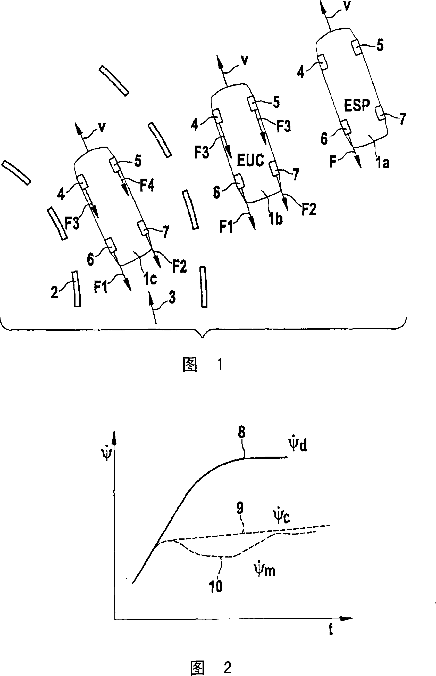
[0020] Figure 1 shows a number of vehicles 1a-1c equipped with various ride dynamics modulation systems and in an understeer condition. The driving dynamics control system keeps the vehicle on its trajectory 3 using different control methods.

[0021] The driving dynamics control system of the right outer vehicle 1 a brakes the inside rear wheel of the curve in a known manner in order to generate a counter-yawing moment towards the inside of the curve. Arrow F indicates the longitudinal force acting on the left rear wheel 6 .

[0022] The driving dynamics control system of the intermediate vehicle 1 b also utilizes a known function (EUC) that simultaneously increases the brake pressure on all four wheels 4 - 7 . Take arrow F 1 and F 2 and F 3 Indicates the braking force acting on wheels 4-7. Braking force F acting on wheels 4 and 5 3 Symmetrical in magnitude and usually higher than the forces acting on the rear axle due to the larger braking coefficient (CP). As mention...


PUM


Abstract

In a method for stabilizing a vehicle in extreme driving situations, in particular when understeering while cornering, multiple wheels are decelerated in order to reduce the driving speed. A maximum cornering force of the wheels and thus a minimal curve radius may be achieved if in particular the rear wheels are decelerated and a higher braking torque is applied on the rear wheels than on the front wheels and in the process in particular the outside front wheel remains highly underdecelerated.

Description

technical field [0001] The invention relates to a method according to the preamble of claim 1 for stabilizing a vehicle in the event of extreme driving dynamics, in particular understeering in curves, and a corresponding method according to the preamble of claim 7 device. Background technique [0002] Driving dynamics control systems, such as ESP or DSC, are used to improve the vehicle's maneuverability and keep the vehicle stable under extreme driving conditions (such as understeer or oversteer when driving in curves). The known system comprises a sensor device for recording measured values ​​of the current driving state of the vehicle, a control unit for adjusting the float angle and / or the yaw ratio by means of a regulation algorithm program, and at least one implementation of an intervention in the driving state of the vehicle mechanism. Depending on the desired actions of the driver, in particular depending on the steering wheel position and the accelerator or brake p...

Claims


Application Information

Patent Timeline
Patent Type & Authority Applications(China)
IPC IPC(8): B60T8/1755
CPCB60T8/1755
Inventor G·格拉夫
Owner ROBERT BOSCH GMBH
Learn More