
low fuel consumption vehicle

A low fuel consumption, vehicle technology, applied in vehicle components, elastic suspension, tire tread/tread pattern, etc., can solve the problems of reduced turning performance, reduced braking performance, small friction coefficient, etc., to improve turning performance, The effect of suppressing the reduction in driving feeling

Inactive Publication Date: 2011-12-28
EQUOS RES
View PDF1 Cites 1 Cited by
  • Summary
  • Abstract
  • Description
  • Claims
  • Application Information

AI Technical Summary

Problems solved by technology

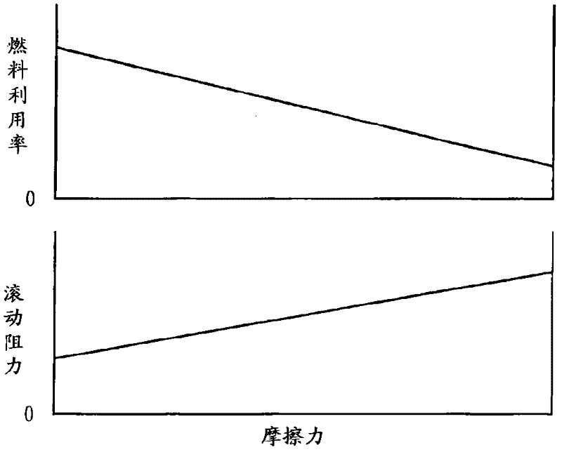
[0007] However, in the above-mentioned conventional vehicles, since the coefficient of friction between the tire and the road surface is small, the braking force that can be generated during braking is small, not only the braking performance is reduced, but also the lateral force that can be generated when turning is small, and the turning performance is not good. also lower

Method used


Image

  • low fuel consumption vehicle
  • low fuel consumption vehicle
  • low fuel consumption vehicle

Examples


Embodiment Construction

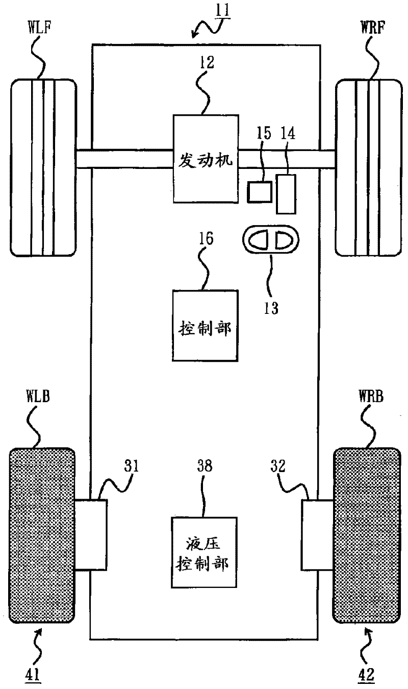
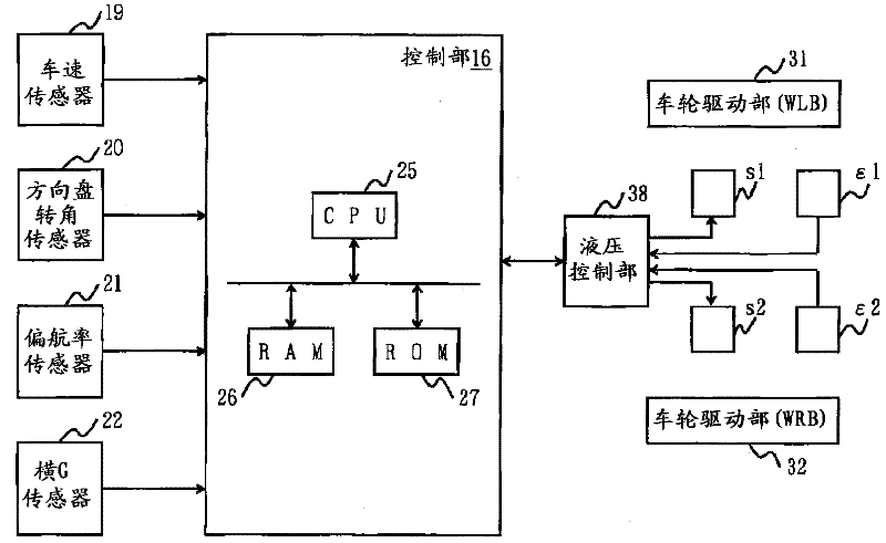
[0052] Hereinafter, embodiments of the present invention will be described in detail with reference to the drawings. In this case, a vehicle that is a fuel-efficient vehicle will be described.

[0053] figure 1 It is a conceptual diagram of a vehicle according to an embodiment of the present invention.

[0054]In the figure, 11 is a vehicle body showing the main body of the vehicle, 12 is an engine as a driving source, and WLF, WRF, WLB, and WRB are front left, front right, and rear left rotatably arranged with respect to the above-mentioned vehicle body 11. As for the wheels on the side and the rear right side, the front wheels are constituted by the wheels WLF and WRF, and the rear wheels are constituted by the wheels WLB and WRB. By driving the above-mentioned engine 12 , the wheels WLF, WRF are rotated in conjunction with each other to function as drive wheels, and the wheels WLB, WRB are driven to rotate as the vehicle travels.

[0055] In addition, 13 is a steering wh...


PUM


Abstract

The fuel efficiency can be improved, and the braking performance and cornering performance can be improved. A vehicle body (11), front wheels and rear wheels rotatably arranged with respect to the body (11), and a wheel drive unit (31) arranged between the rear wheels and the body (11) and imparting a camber angle to the rear wheels , 32). The coefficient of friction between the tires of the rear wheels and the road surface is smaller than the coefficient of friction between the tires of the front wheels and the road surface. Since the coefficient of friction between the respective tires of the rear wheels and the road surface is smaller than that between the respective tires of the front wheels and the road surface, fuel efficiency can be improved. In addition, since the coefficient of friction between each tire of the front wheels and the road surface is large, acceleration and braking performance can be sufficiently improved. In addition, since the rear wheel is provided with a camber angle, a lateral force can be generated, a lateral resistance force can be generated, and turning performance can be improved.

Description

technical field [0001] The invention relates to vehicles with low fuel consumption. Background technique [0002] Conventionally, vehicles travel by rotating wheels. In this case, the greater the friction force generated between the tires of each wheel and the road surface, the greater the force of the tires grabbing the road surface, that is, the greater the grip force, which can improve the acceleration and braking performance of the vehicle. The rolling resistance generated in the opposite direction of the tire in the rolling direction increases, and thus the fuel efficiency deteriorates. On the other hand, the smaller the above-mentioned frictional force, the smaller the tire's grip on the road surface, and the lower the acceleration and braking performance, but the rolling resistance is small, and the fuel efficiency is good. [0003] Also, when the driver operates the steering wheel to change the orientation of the tires, a lateral force is generated in a direction p...

Claims


Application Information

Patent Timeline
IPC IPC(8): B60G17/015B60C5/00B60C11/00B60G17/016
Inventor 塚本一雅安藤正夫堀口宗久阿部稔
Owner EQUOS RES
Learn More