Tenoning clamping mechanism

A clamping mechanism and tenoning technology, applied in the direction of mortising machines, slotting machines, wood processing equipment, etc., can solve the problems of scattered pressing force and insufficient tenoning stability, and achieve simple structure and provide tenoning Accuracy, Quantity Saving Effect

Inactive Publication Date: 2015-03-04
安吉胜达竹木制品有限公司
View PDF9 Cites 1 Cited by
  • Summary
  • Abstract
  • Description
  • Claims
  • Application Information

AI Technical Summary

Problems solved by technology

However, the pressing force provided by the two pressing plates is relatively scattered, and the tenoning stability is not enough

Method used


Image

  • Tenoning clamping mechanism
  • Tenoning clamping mechanism
  • Tenoning clamping mechanism

Examples


Embodiment 1

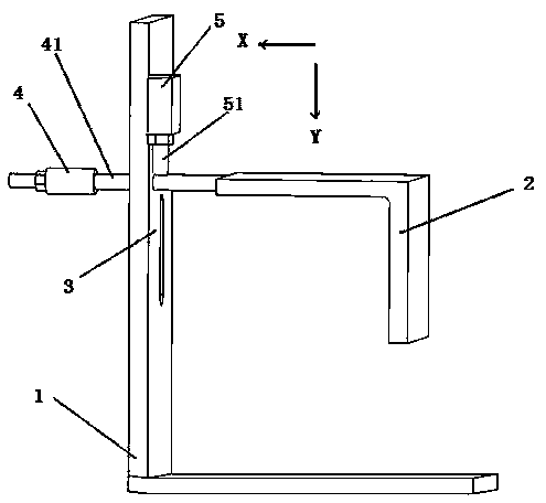
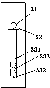
[0033] Such as figure 1 , The tenon clamping mechanism includes an L-shaped workbench frame 1, a pressing plate 2, a first cylinder 4, and a second cylinder 5. A movable area 3 is provided on the longitudinal side of the workbench frame 1, and the movable area 3 includes a horizontal movable hole 31, a telescopic baffle 32 and a longitudinal movable groove 33. The pressing plate 2 is an integrally formed ??-shaped structure, the lateral side of the pressing plate 2 is connected with the cylinder shaft 41 of the first cylinder 4, and the cylinder shaft 42 of the first cylinder 41 passes through the Horizontal movable holes 31 are provided. The second cylinder 5 is arranged longitudinally on the workbench frame 1, and its second cylinder shaft 51 is directly above the first cylinder shaft 41. In order to make the second cylinder shaft 51 apply uniform and stable pressure to the first cylinder shaft 41 In the case of longitudinal force, an arc-shaped part is provided at the end o...

Embodiment 2

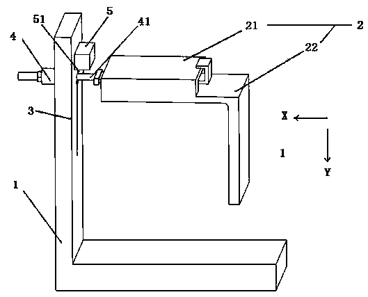
[0037] Such as figure 2 The tenon clamping mechanism includes an L-shaped workbench frame 1, a pressing plate 2, a first cylinder 4, and a second cylinder 5. A movable area 3 is provided on the longitudinal side of the workbench frame 1, and the movable area 3 includes a horizontal movable hole 31, a telescopic baffle 32 and a longitudinal movable groove 33. The pressing plate 2 includes a groove part 21 and a ??-shaped structure 22, both of which are integrally formed and detachable structures. The groove part 22 is arranged on the upper side of the lateral side of the pressing plate 2 and is connected to the first cylinder 4, and a gusset plate that is fitted with the groove part 22 is fixedly connected to the first cylinder shaft 41 side. When the tenon clamping mechanism works, the pressing plate 2 and the buckle plate are connected in cooperation. The cylinder shaft 41 of the first cylinder 4 is arranged transversely through the horizontal movable hole 31, the second cyl...


PUM


Abstract

The invention relates to a tenoning clamping mechanism, and belongs to the technical field of wood industry processing. The tenoning clamping mechanism comprises a worktable frame, a pressing plate, a first air cylinder and a second air cylinder, wherein the worktable frame is used for supporting a tenoning workpiece, the pressing plate is integrally formed, and is used for providing upward pressing force and lateral pressing force for the tenoning workpiece, the first air cylinder and the second air cylinder are used for providing pressing power, the worktable frame is in an L shape, the longitudinal edge of the worktable frame is provided with a movable area, an air cylinder shaft of the first air cylinder transversely penetrates through the movable area and is connected with the pressing plate, the second air cylinder is arranged at the longitudinal edge of the worktable frame, an air cylinder shaft of the second air cylinder longitudinally acts on the shaft of the first air cylinder, and the first air cylinder and the pressing plate are moved along the longitudinal axis direction of the movable area. The tenoning clamping mechanism has the advantages that the structure is simple; by arranging the integral forming pressing plate, the number of pressing plates is reduced, the operation of operators is convenient, the upward pressing force, lateral pressing force and edge and corner force are simultaneously provided, the tenoning workpiece is clamped, and the tenoning accuracy is provided.

Description

Technical field [0001] The invention relates to the technical field of wood processing, in particular to a tenon clamping mechanism. Background technique [0002] In the past, a manual method was used to do tenoning on wooden pieces, using chisels and iron saws to do tenoning. The disadvantages were low efficiency and inaccurate processing dimensions. At present, in the process of processing the tenon, it is generally processed by a tenoning machine. The existing tenoning machine, such as the utility model patent ZL95216554.6, generally uses a cylinder to control two pressure plates to act on the tenoning work piece, one as the upper pressure plate Provides the upper pressing force, and the other serves as the side pressing plate to provide the side pressing force to realize the firm clamping of the tenoning work piece, thereby improving the subsequent tenoning accuracy. However, the pressing force provided by the two pressing plates is relatively dispersed, and the tenoning...

Claims


Application Information

Patent Timeline
Patent Type & Authority Applications(China)
IPC IPC(8): B27F5/00
CPCB27F5/00
Inventor 姚仲民
Owner 安吉胜达竹木制品有限公司
Why Eureka
Try Eureka