Automatic parking brake having a slip controller

a technology of automatic parking brake and controller, which is applied in the direction of braking system, vehicle position/course/altitude control, instruments, etc., can solve the problems of braked wheels being too long to lock, poor controllability of electromechanical systems, and substantially slower mechanical components response, and achieve positive effects on control respons

Active Publication Date: 2015-03-31
ROBERT BOSCH GMBH
View PDF21 Cites 1 Cited by
  • Summary
  • Abstract
  • Description
  • Claims
  • Application Information

AI Technical Summary

Benefits of technology

[0006]Example embodiments of the present invention provide for performing a slip control on the braked wheels and designing the corresponding controller in such a way that when controlling the slip on a first wheel, the wheel slip of a second wheel is taken into account. For example, depending on the magnitude of the wheel slip of the other wheel, a decision is made whether or not the braking force on the controlled (first) wheel may be increased. Thus, the possibility that both wheels lock at the same time or have too much slip is eliminated. The cornering force is thus maintained at least on one wheel.
[0008]In example embodiments, the wheel slip of another wheel is ascertained and an increase of the braking force on the controlled (first) wheel is allowed only if the wheel slip of the other wheel is lower than a predefined threshold value. The threshold value may be, for example, between 3% and 5% wheel slip. The threshold value may be, for example, approximately 4% wheel slip. This makes it possible to prevent the two wheels from locking at the same time and to allow them to continue to take up cornering force.
[0011]In example embodiments, after a braking operation is triggered, the control operation on the left and right wheel is started asynchronously. That is, the electric motors are triggered in a time-delayed fashion. This has positive effects on the control response since it reduces the danger of an oscillating system in which both wheel brakes are synchronously opened or closed.

Problems solved by technology

A difficulty of such parking brake systems using electric motors is that the response of the mechanical components is substantially slower than in a hydraulic parking brake system.
This results in a relatively poor controllability of the electromechanical systems.
This may cause the braked wheels to lock too long while being controlled.
In a critical driving situation, for example, when oversteering or understeering while cornering, a vehicle may lose its cornering force.

Method used


Image

  • Automatic parking brake having a slip controller
  • Automatic parking brake having a slip controller
  • Automatic parking brake having a slip controller

Examples


Embodiment Construction

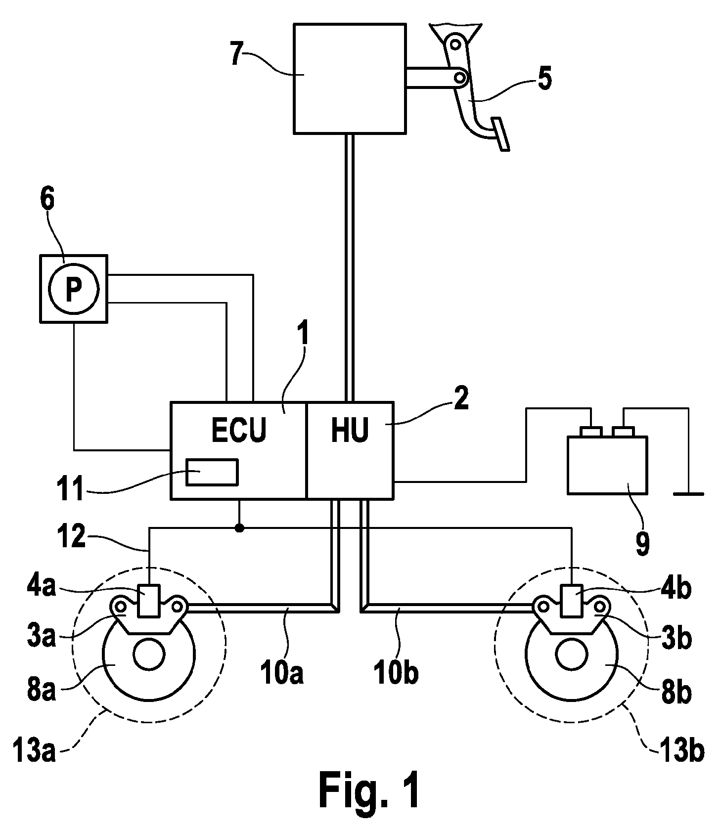
[0016]FIG. 1 shows a block diagram of a hydraulic braking system having an automatic parking brake according to an embodiment of the present invention. In an available manner, the braking system includes a foot brake pedal 5, which acts together with a main brake cylinder via a brake booster (combined in block 7). The brake pressure produced by the driver and amplified is conducted via a hydraulic unit 2, which is designed to perform a slip control, and brake lines 10a, 10b to wheel brakes 3, 8. Wheel brakes 3, 8 are implemented in this example embodiment as disk brakes, which respectively include a brake caliper 3 and a brake disk 8.

[0017]The automatic parking brake includes an operating element 6 (e.g. a push-button switch) for activating and deactivating the parking brake, a control unit 1, connected to push-button switch 6, in which a parking brake algorithm having a slip controller 11 is stored, and multiple electric motors 4a, 4b, which are respectively mounted on a brake cali...


PUM


Abstract

A system, method and device are provided which relate to an automatic parking brake for motor vehicles having multiple brake actuators and an operating element for operating the parking brake. In embodiment, the brake actuators are connected to a controller, which is able to perform a wheel-specific slip control when a critical driving situation occurs. For example, a simultaneous locking and the loss of the cornering force can be prevented by a controller. The controller is designed in such a way so that when controlling the slip on a first wheel, the slip (λ2) of a second wheel is taken into account.

Description

FIELD OF INVENTION[0001]The present invention relates to an automatic parking brake for motor vehicles, a method for controlling slip, and a control unit having a slip controller.BACKGROUND INFORMATION[0002]Automatic parking brakes (APB) typically include an operating element such as, e.g., a push-button switch by which the parking brake may be locked or released. When the operating element is actuated, a control unit connected to it recognizes the parking brake command and accordingly controls an actuator such as, e.g., a hydraulic pump or an electric motor in order to build up braking force on the wheels of the vehicle or to release the brake.[0003]The following considers systems in which electric motors (having gear units) are situated directly on the wheel brakes (so-called “motor on caliper”). Such parking brake systems are typically designed so that the driver may operate them when the vehicle is at a standstill and while driving. The possibility of an operation while driving ...

Claims


Application Information

Patent Timeline
Patent Type & Authority Patents(United States)
IPC IPC(8): B60T8/84B60T7/12B60T8/1761B60T8/32F16D65/28
CPCB60T8/17616B60T7/12B60T8/32
Inventor BAEHRLE-MILLER, FRANKBLATTERT, DIETERBOGRAD, VITALIY
Owner ROBERT BOSCH GMBH
Why Eureka
Try Eureka