Montejus equipped with injector

A technology of ejector and liquid device, applied in the field of pressure gas lifter

Active Publication Date: 2010-07-07
洛阳百克特科技发展股份有限公司
View PDF0 Cites 0 Cited by
  • Summary
  • Abstract
  • Description
  • Claims
  • Application Information

AI Technical Summary

Problems solved by technology

Due to the disadvantages of the pneumatic pump with this structure, such as many rotating parts, easy wear and tear, difficult maintenance, high noise, high water quality requirements, overheating when running dry, no idling allowed, and short service life, etc. It will increase the user's use cost, and there are certain safety hazards
Doesn't work well when the water level is low

Method used


Image

  • Montejus equipped with injector
  • Montejus equipped with injector

Examples


Embodiment Construction

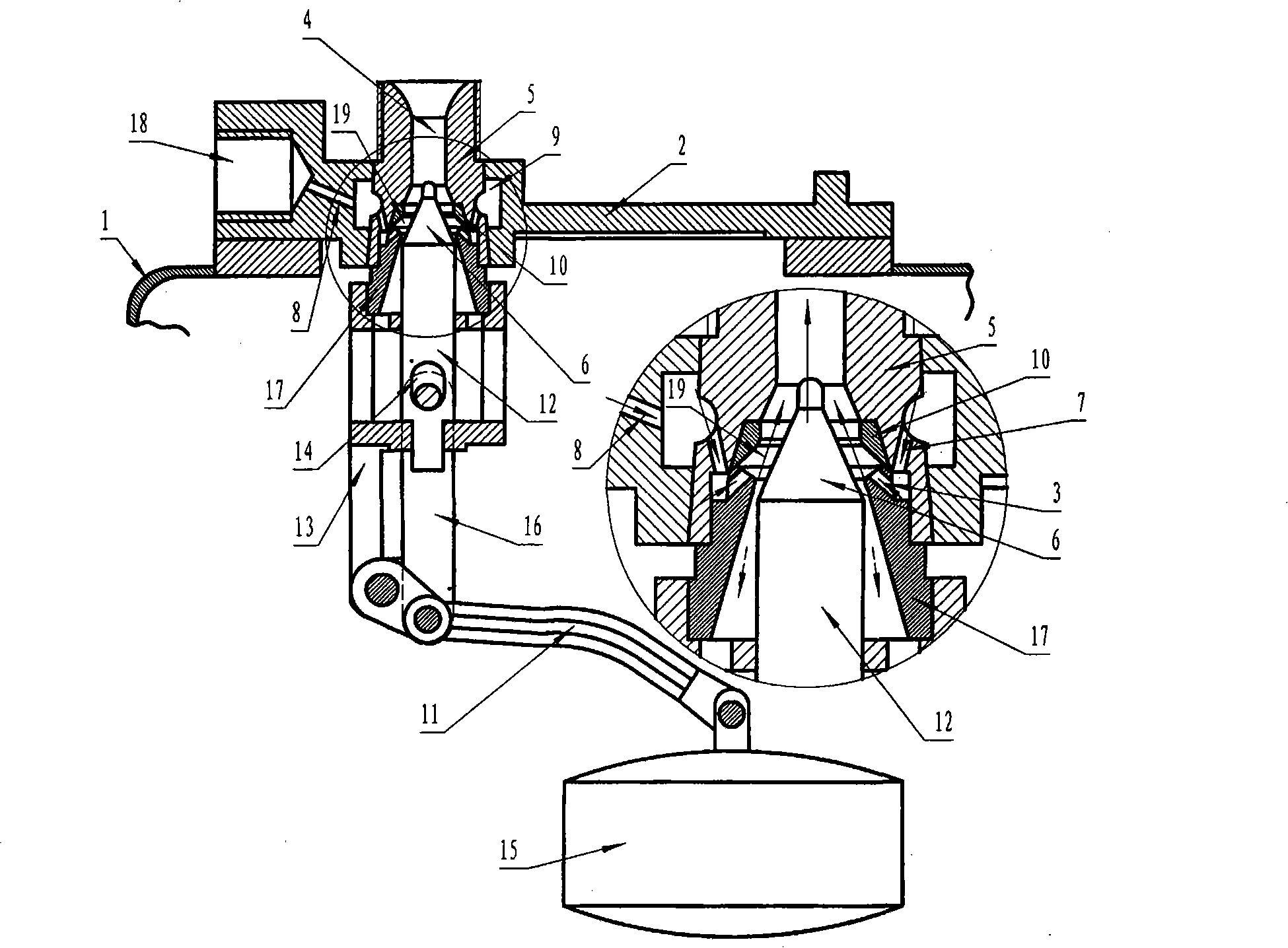
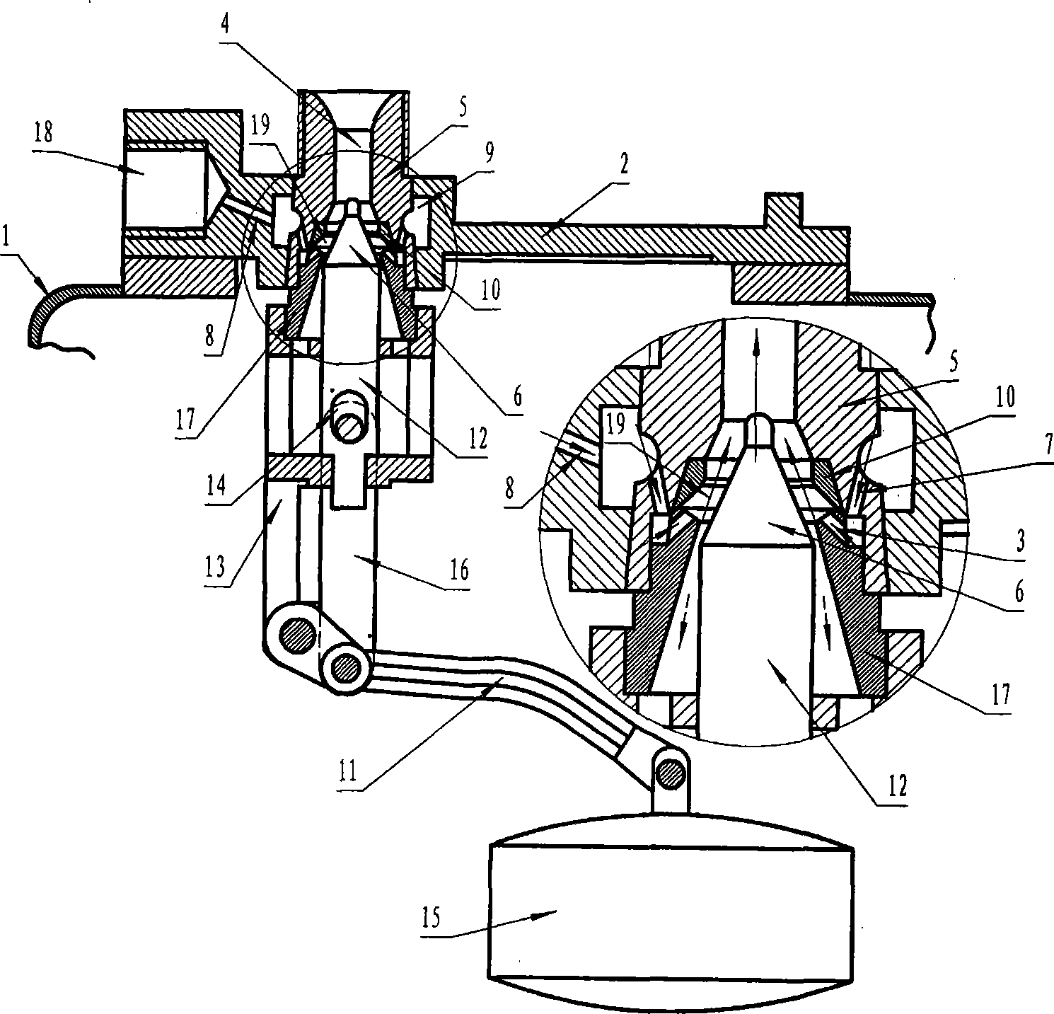
[0010] In conjunction with accompanying drawing, provide embodiment of the present invention as follows:

[0011] As shown in the figure: In this embodiment, an installation opening is opened on the upper end of the pump body 1, which is sealed by the control cover plate 2.

[0012] The control cover plate 2 is provided with a compressed air inlet 18, an air intake channel 8 and a tapered installation hole, the installation hole runs through the upper and lower ends of the control cover plate 2, and the middle part is an annular air chamber 9, which is connected with the annular air chamber 9. The compressed air inlet 18 communicates with the air inlet passage 8, and the pipe diameter of the air inlet passage 8 is smaller than the pipe diameter of the compressed air inlet 18, so as to increase the pressure of the gas and increase the flow rate. The distribution box is installed on the tapered mounting hole of the control cover plate 2. The distribution box is mainly composed ...


PUM


Abstract

The invention relates to a pneumatic fluid lifter with an injector. On a pump body, a control console is installed, which is provided with an compressed air inlet, an air admission channel and an installation hole, in which a distribution box is installed. The compressed air enters into the distribution box through a control cover board, is injected into the exhaust port through an injection hole; negative pressure is produced in the pump body to suck out the air in the pump body, the water-sucking one-way valve opens, the water is sucked into the pump from the pump bottom; the float in the pump raises to push the cone of the pneumatic valve to rise, when the water level reaches to the designed height, the cone closes the exhaust port, the compressed air transfers into the press-in pump, the water-suction port closes, the water discharging port opens, the water is pressed out from the pump body. As the pneumatic fluid lifter has no rotary part, compressed air is used to suck and discharge water, and water is sucked and discharged automatically depending upon the water level, so un-attended operation is achieved, labor is saved. The pneumatic fluid lifter is of simple structure, easy to maintain, low cost, and can work normally at low water level. The pneumatic fluid lifter has no electric apparatus, is explosive proof, is applicable for working in pits of coal mines and environment with explosive gas.

Description

technical field [0001] The invention belongs to the technical field of compressed air lifter (pneumatic pump), and mainly relates to a compressed air lifter equipped with an injector. It has the functions of conveying pump body liquid, exhausting and sucking liquid. Background technique [0002] Existing wind-driven pumps are mainly based on the wind-driven turbine type, which is mainly composed of pump outer body, wind wheel, water wheel, main shaft and other components. When working, the compressed air blows the wind wheel, and the wind wheel drives the water wheel to rotate through the main shaft to lift the liquid. Due to the disadvantages of the pneumatic pump with this structure, such as many rotating parts, easy wear and tear, difficult maintenance, high noise, high water quality requirements, overheating when running dry, no idling allowed, and short service life, etc. Can increase the use cost of the user, there is certain potential safety hazard. Does not work ...

Claims


Application Information

Patent Timeline
Patent Type & Authority Patents(China)
IPC IPC(8): F04F1/02
Inventor 张文斌邓涛张晓雷潘锡志
Owner 洛阳百克特科技发展股份有限公司
Why Eureka
Try Eureka