Method for improving zero bias temperature sensitivity of optical fiber gyroscope

A temperature sensitivity, fiber optic gyroscope technology, applied in Sagnac effect gyroscopes and other directions, can solve the problems of high power consumption, unapplied, complex structure, etc., to eliminate the zero offset change and improve the temperature sensitivity performance.

Inactive Publication Date: 2008-01-23
ZHEJIANG UNIV
View PDF0 Cites 11 Cited by
  • Summary
  • Abstract
  • Description
  • Claims
  • Application Information

AI Technical Summary

Problems solved by technology

[0005] The temperature sensitivity of the zero bias of the fiber optic gyroscope deteriorates the static index of the fiber optic gyroscope when it is applied in a wide temperature range. A temperature-related error function is superimposed on its output angular velocity signal, which limits its application. The existing technology is to use Additional temperature control system fiber optic gyroscope is used for temperature control to make it work in a quasi-constant temperature environment, but this technology has serious defects, requiring a large volume, huge power consumption, and complex structure temperature control system, in certain volume, weight, power consumption Cannot be used in demanding systems

Method used


Image

  • Method for improving zero bias temperature sensitivity of optical fiber gyroscope

Examples


Embodiment Construction

[0030] Below in conjunction with accompanying drawing and embodiment the present invention will be further described:

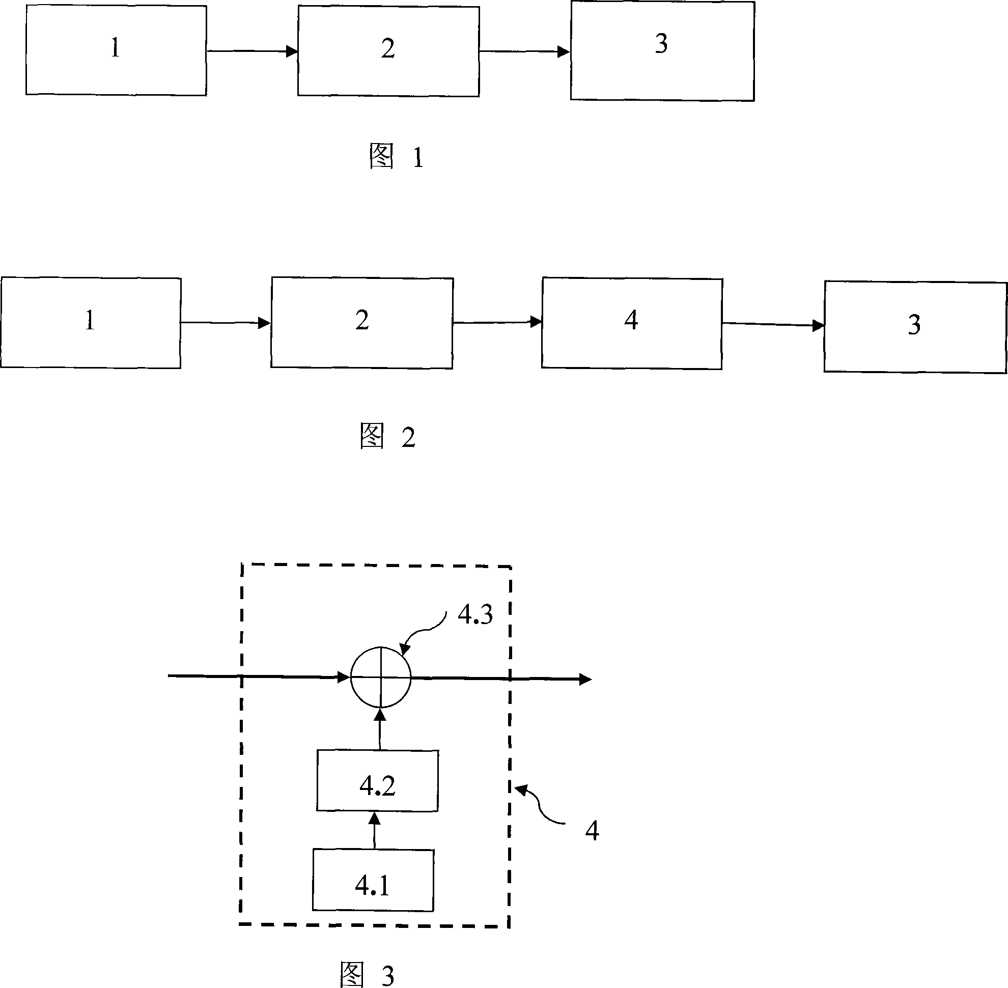
[0031] Figure 1 shows the signal processing structure of the fiber optic gyroscope without a compensator, which includes three parts: sampling channel 1, central processing unit 2 and communication interface 3, where sampling channel 1 realizes the conversion of the optical signal from the optical fiber gyroscope optical system into The electrical signal is sent to the central processing unit 2, and the central processing unit 2 performs demodulation, filtering and other calculations after receiving the signal from the sampling channel 1 to obtain the speed of the system where the fiber optic gyroscope is located, and sends the speed to the communication interface 3, through Communication interface 3 is uploaded to the host computer.

[0032] Figure 2 shows the structure of the fiber optic gyroscope signal processing part after adding the compensator, which i...


PUM


Abstract

The invention discloses a method for improving the zero-shift temperature sensibility of an optic-fiber gyro. A sampling channel converts the optic signals from the optic system of the optic-fiber gyro into electric signals, and sends them to the central processor, which after processing outputs rotation signals through a communication interface to outside; between the central processor and the communication interface, a compensator is placed. Based on a zero-shift temperature sensibility model got by measurements beforehand, the zero-shift change caused by temperature can be suppressed only by the compensator without using a huge and complicated temperature controlling equipment and additional power, this eliminates zero-shift change caused by temperature, improves the temperature sensibility of zero shift for the optic-fiber gyro, so that the optic-fiber gyro can be used in wider temperature range, and maintain static performance as like operating under a thermostatic environment. The invention expands the application field of optic-fiber gyros.

Description

technical field [0001] The invention relates to a signal processing method in an optical fiber gyroscope sensor, in particular to a method for improving the performance of the optical fiber gyroscope zero bias temperature sensitivity. Background technique [0002] The fiber optic gyroscope is an angular velocity sensor based on the optical Segneck effect. By detecting the phase of the Segneck light generated by the fiber optic interferometer, the angular velocity of the system, that is, the rotational speed [0003] Due to the non-ideal performance of each component of the fiber optic gyroscope, its comprehensive effect makes the output signal of the fiber optic gyroscope non-zero when the input is zero angular velocity, but has a certain bias. This bias is called the zero bias of the fiber optic gyroscope, or zero bias for short. . The zero bias is caused by many different factors, and it will change with the environment in different application environments. The nature of...

Claims


Application Information

Patent Timeline
Patent Type & Authority Applications(China)
IPC IPC(8): G01C19/72
Inventor 陈杏藩刘承舒晓武胡慧珠
Owner ZHEJIANG UNIV
Why Eureka
Try Eureka