Optical method for detecting defect on inner wall of holes

A technology for hole inner wall and defect, which is applied in the field of optical measurement of hole inner wall defect, can solve the problems of low environmental requirements, inability to detect wear, scratches, etc., achieve effective calculation, facilitate post-processing, and improve detection speed.

Inactive Publication Date: 2008-01-23
BEIJING INSTITUTE OF TECHNOLOGYGY
View PDF0 Cites 26 Cited by
  • Summary
  • Abstract
  • Description
  • Claims
  • Application Information

AI Technical Summary

Problems solved by technology

[0004] In response to this situation, people have proposed an optical detection method. The so-called optical detection method belongs to non-contact detection. Compared with traditional magnetic particle inspection, ultrasonic flaw detection and other methods, the optical detection method has low environmental requirements, strong anti-interference and detection speed. Therefore, the optical detection method has been more and more widely used in the deep hole detection: Li Jiangxiong et al. in the article "Three-dimensional reconstruction of the inner surface of the microtube hole based on structured light" (Journal of Instrument and Instrumentation, Vol.27, No.3, 2006, pp.254-259) provides a deep hole inner surface reconstruction technology based on structured light. The detection system consists of a pipeline robot, a shape detector and a curvature detector, but this method can only Detect the geometric deformation of the inner surface, and cannot detect surface defects such as wear and scratches

Method used


Image

  • Optical method for detecting defect on inner wall of holes
  • Optical method for detecting defect on inner wall of holes
  • Optical method for detecting defect on inner wall of holes

Examples


Embodiment Construction

[0030] Below in conjunction with accompanying drawing, the present invention will be further described:

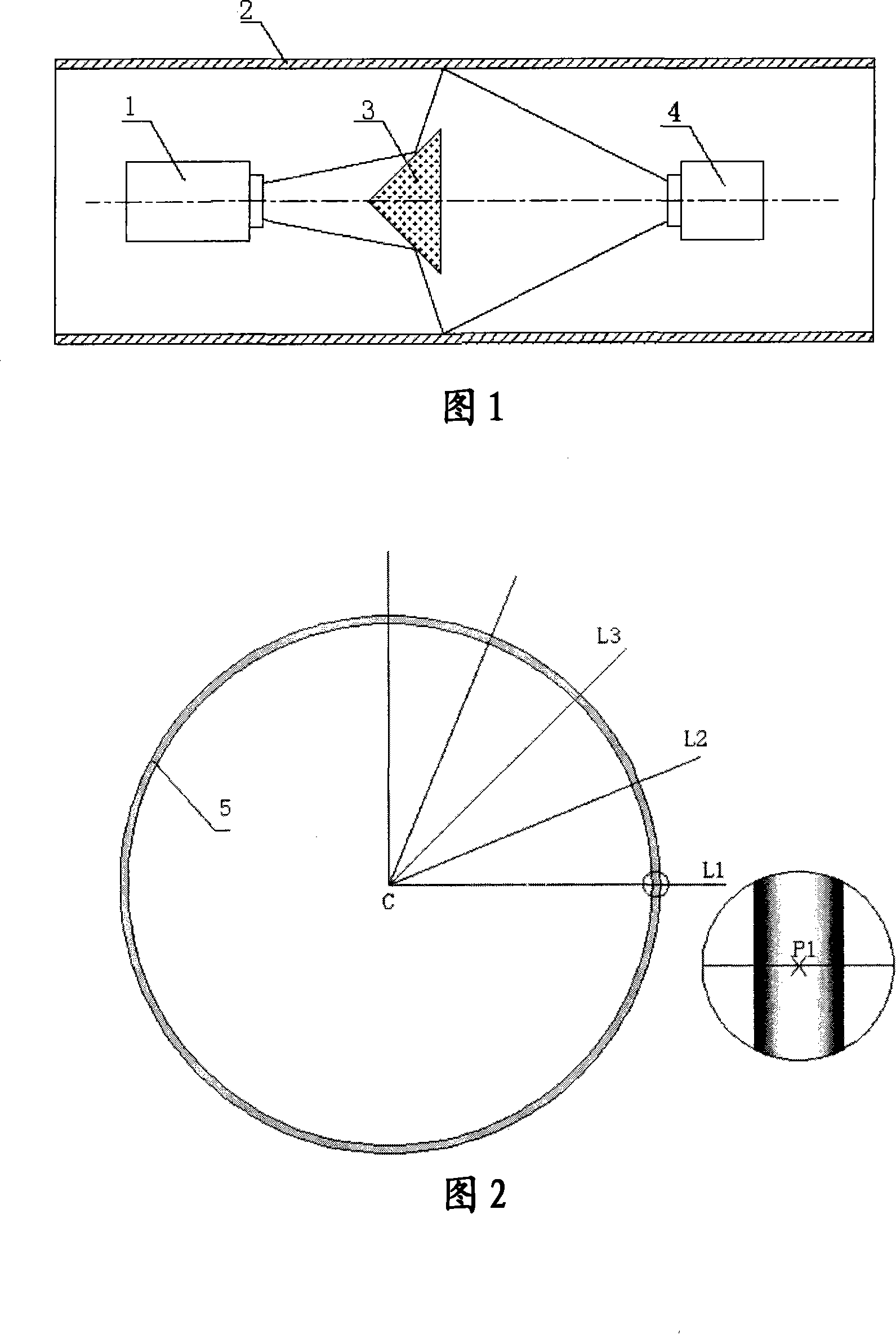
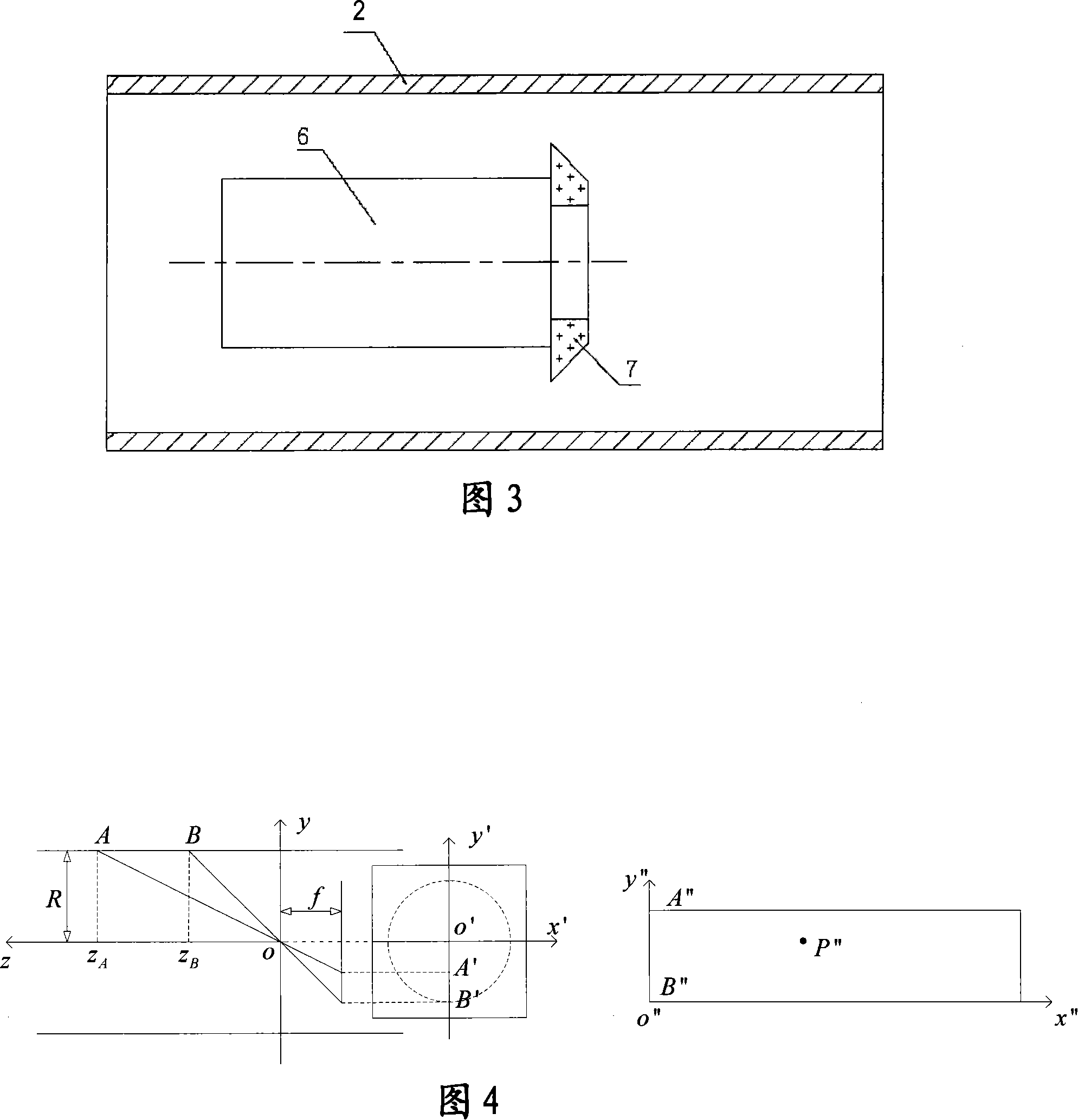
[0031] Fig. 1 is a schematic diagram of the measurement method of the ring laser vision sensor. The light cone projected by the ring laser 1 intersects with the inner wall of the deep hole after passing through the reflector mirror 3 to form a three-dimensional curve in space. The CCD camera acquires the image of the three-dimensional curve to calculate the cross-sectional size and Processing, specific calculation as shown in Figure 2: C in Figure 2 is the initial center of the set, 5 is the contour curve on the cross-sectional view, with C as the vertex as the ray L1 intersects the contour curve, because the contour curve has a certain width, and The brightness distribution on the curve is uneven, the brightness in the middle is high, and the brightness values ​​​​on both sides are low. After intersecting with L1, a line segment is formed. The brightness distribution on th...


PUM


Abstract

The invention provides a method for detecting any defect in the inner wall of a hole by an optic way, which comprises the following procedures: a light pickup picks up an image formed by laser after reflecting on the inner wall of the hole, so as to get the depth at any point on the inner wall of the hole; the light pickup picks up an image formed by an illumination light after reflecting on the inner wall of the hole, so as to get the explored image of the inner wall of the hole and get the 2D sizes of the defect; and the 3D info on the defect is obtained by combining above two dimensions. By combining laser measurement with illumination light measurement, it is not only possible to get the 2D size of the defect, but also is possible to get the depth of the defect, so as to achieve 3D measurement of the defect; the use of a non-contact measuring way avoids any contact wear between a probe and the object to be measured, and improves the inspection speed.

Description

technical field [0001] The invention relates to a method for optically measuring defects on the inner wall of a hole. Background technique [0002] In the prior art, it is often necessary to detect the inner wall of the hole, especially the deep hole, which has a large ratio of hole depth to hole diameter, and has a wide range of applications in actual production, life and military fields, such as transporting natural gas Due to long-term use, the inner walls of these deep-hole parts are prone to wear, scratches, and fall-off defects, which bring safety hazards to actual production and use. Therefore, The inner wall must be regularly inspected to detect potential defects early, and carry out targeted emergency repairs and maintenance in a planned manner according to the size, nature and distribution of defects to reduce unnecessary losses. In addition, the detection of the inner wall provides a scientific basis for the research and processing of deep hole parts. [0003] I...

Claims


Application Information

Patent Timeline
Patent Type & Authority Applications(China)
IPC IPC(8): G01N21/954
Inventor 肖定国徐春广冯忠伟朱文娟郝娟周世圆
Owner BEIJING INSTITUTE OF TECHNOLOGYGY
Why Eureka
Try Eureka