Whirling traveling-wave tube amplifier coupling input structure and its design method

A technology of traveling wave tube amplifier and traveling wave amplifier, which is applied in the microwave field, can solve the problems of high standing wave in the working frequency band and narrow coupling input bandwidth, achieve good transmission performance and meet the requirements of the whole tube assembly

Inactive Publication Date: 2008-01-23
INST OF ELECTRONICS CHINESE ACAD OF SCI
View PDF0 Cites 15 Cited by
  • Summary
  • Abstract
  • Description
  • Claims
  • Application Information

AI Technical Summary

Problems solved by technology

[0004] The purpose of the present invention is to solve the problem that the coupling input bandwidth of the traditional design scheme of the coupling input structure is narro...

Method used


Image

  • Whirling traveling-wave tube amplifier coupling input structure and its design method
  • Whirling traveling-wave tube amplifier coupling input structure and its design method
  • Whirling traveling-wave tube amplifier coupling input structure and its design method

Examples


Embodiment Construction

[0037] The present invention will be described in detail below in conjunction with the accompanying drawings. It should be noted that the described embodiments are only intended to facilitate the understanding of the present invention, rather than limiting it in any way.

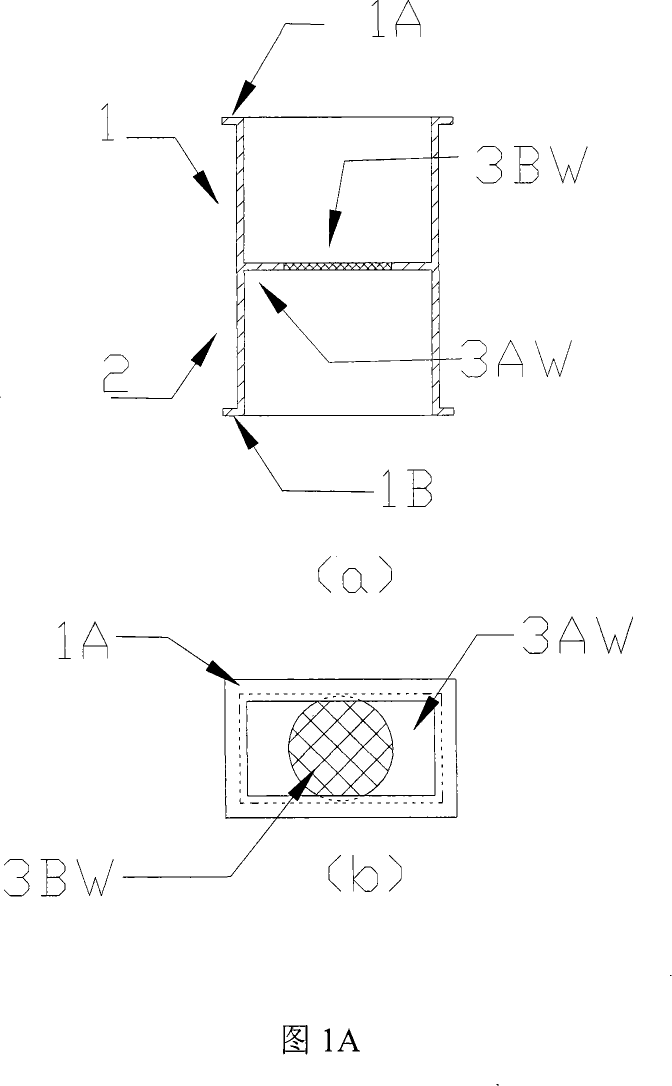
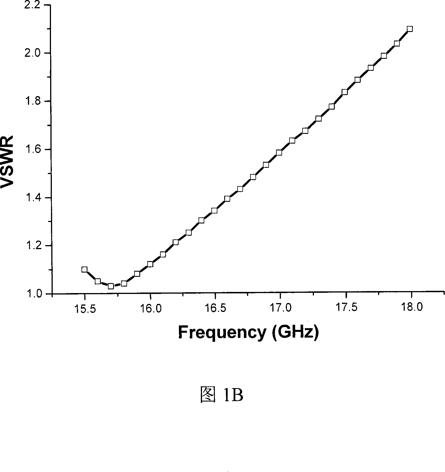
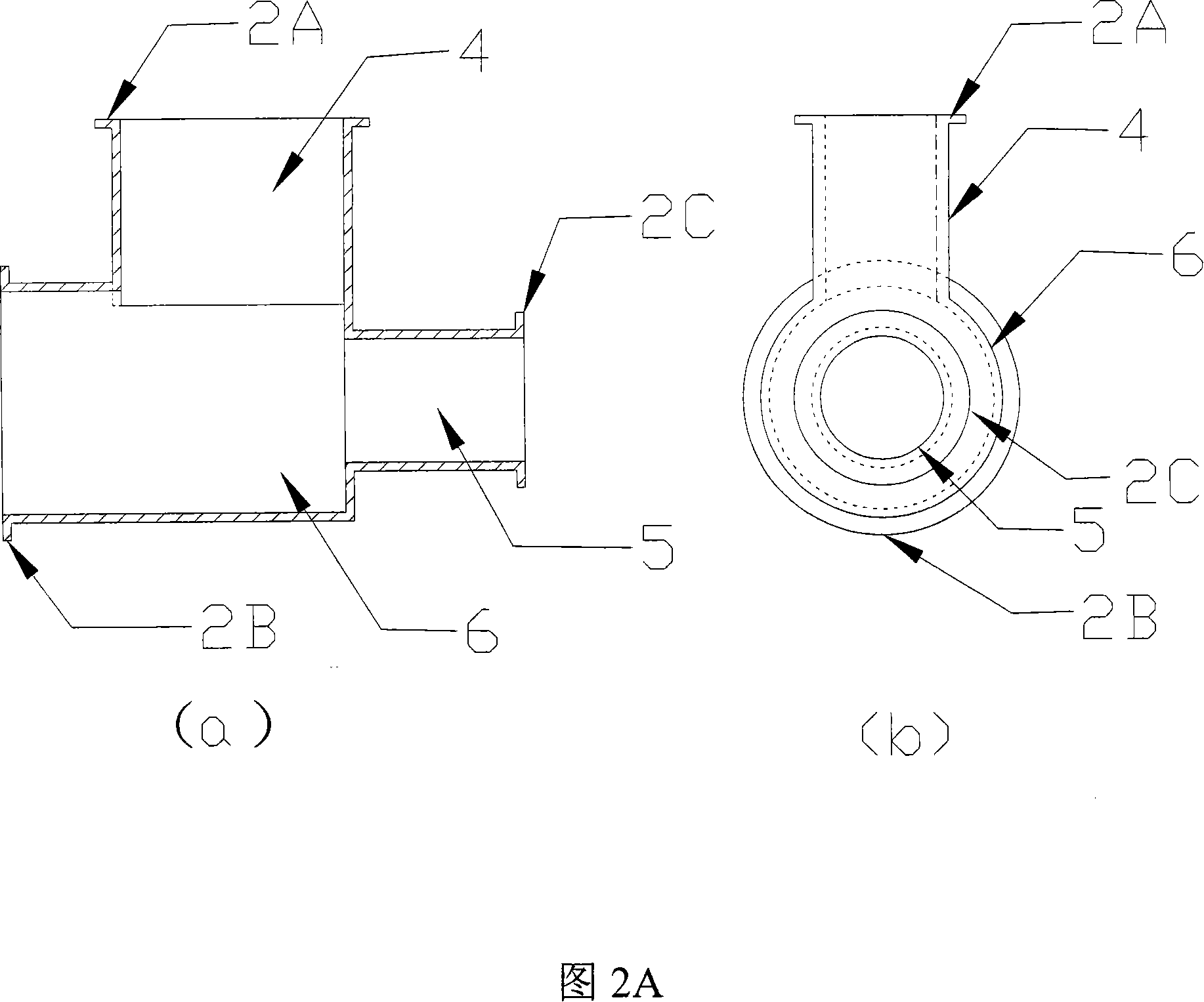
[0038] In order to help a better understanding of the present invention, specific embodiments of the present invention will be described below with reference to the accompanying drawings. The drawings are divided into two categories: structural diagrams and standing wave ratio diagrams. FIG. 1A, FIG. 2A, FIG. 3A, FIG. 4A and FIG. 5A are corresponding structural diagrams. The structure diagram is mainly used to describe the specific details of the structure. The structure diagram usually consists of two parts (a) and (b), where (a) is a section view of the corresponding structure, and (b) is a right view or top view of the corresponding structure. FIG. 1B , FIG. 2B , FIG. 3B , FIG. 4B and FIG. 5B are standin...


PUM


Abstract

The present invention relates to a coupling input structure and a design method for a gyro traveling-wave tube amplifier (gyro-TWTA). Wherein, the structure comprises a vacuum isolating window, a first wave-guide and a matched wave-guide, all of which are connected together with flanges. The method includes that based on resonance characteristic of the vacuum isolating window, the coupling input structure is matched on two frequency points according to range of a working band. The vacuum isolating widow is adjusted to make a resonance frequency land into the working band, thus setting the resonance frequency as a first reference frequency. A former level of combined wave-guide is created and composed of the first wave-guide and the matched wave-guide cascaded in the first reference frequency. And then, the former level of combined wave-guide is matched and cascaded with the vacuum isolating window, thus obtaining a working bandwidth of the gyro-TWTA coupling input structure. Two points of minimum standing wave ratio are provided in the working band. As the working frequency is approximate to a cut-off frequency of a main mutual loop for the gyro-TWTA, excellent transmission performance is provided. The compact structure can be directly made with current techniques.

Description

technical field [0001] The invention belongs to the field of microwave technology, and particularly relates to high-power microwave devices. Background technique [0002] The high-power and wide-bandwidth capability of the cyclotron traveling-wave tube in the millimeter wave band makes it a coherent radiation source that has attracted much attention among high-power microwave sources, and has been widely used in radar and communication systems. The working frequency band of the gyro-traveling-wave tube amplifier is close to the cut-off frequency of its main interaction loop, and the main function of its coupling input system is to efficiently and stably input the low-power driving microwave into the main interaction loop of the gyro-traveling wave tube amplifier. [0003] For the gyrotron TWTs working in different modes, the coupling-in structures are different. Although many countries have successfully carried out experiments on gyrotron traveling wave tube amplifiers, mos...

Claims


Application Information

Patent Timeline
IPC IPC(8): H01P5/00H01P3/00
Inventor 杜朝海刘濮鲲耿志辉
Owner INST OF ELECTRONICS CHINESE ACAD OF SCI
Why Eureka
Try Eureka