Sealing device

A technology for sealing devices and sealing elements, which is applied to the sealing of engines, non-mechanical drive clutches, fluid drive clutches, etc. It can solve problems such as large fitting installation force, deformation of core 104, and increased output power, so as to improve resistance , the effect of preventing detachment

Inactive Publication Date: 2008-01-23
NOK CORP
View PDF1 Cites 0 Cited by
  • Summary
  • Abstract
  • Description
  • Claims
  • Application Information

AI Technical Summary

Problems solved by technology

[0004] However, as shown in FIG. 9, in order to install the sealing member 101 on the piston member 102, the core 104 bonded with the sealing portion 103 is fitted to the piston member 102. Since the thickness t of the core 104 0 The thickness of the flange part 104a and the cylindrical part 104b is the same, the fitting installation force when fitting the core 104 to the piston element 102 is large, and the fitting installation force itself has a large deviation, so the core 104 is deformed The problem
[0005] In addition, in order to control the deviation of the fitting and mounting force, it is necessary to strictly control the tolerance of the fitting dimension of the piston element and the core, so it is necessary to add processing steps such as turning, and the processing accuracy must also be improved, which will cause the problem of increased manufacturing costs.
In addition, when the fitting and mounting force is large, the output power of the auxiliary equipment for fitting the core to the piston element also increases, and there is also a problem that the manufacturing cost increases.

Method used


Image

  • Sealing device
  • Sealing device
  • Sealing device

Examples


Embodiment Construction

[0033] Hereinafter, preferred embodiments of the present invention will be described with reference to the drawings. However, the scope of the present invention is not limited to the specific description, nor is it limited to the contents described in these embodiments.

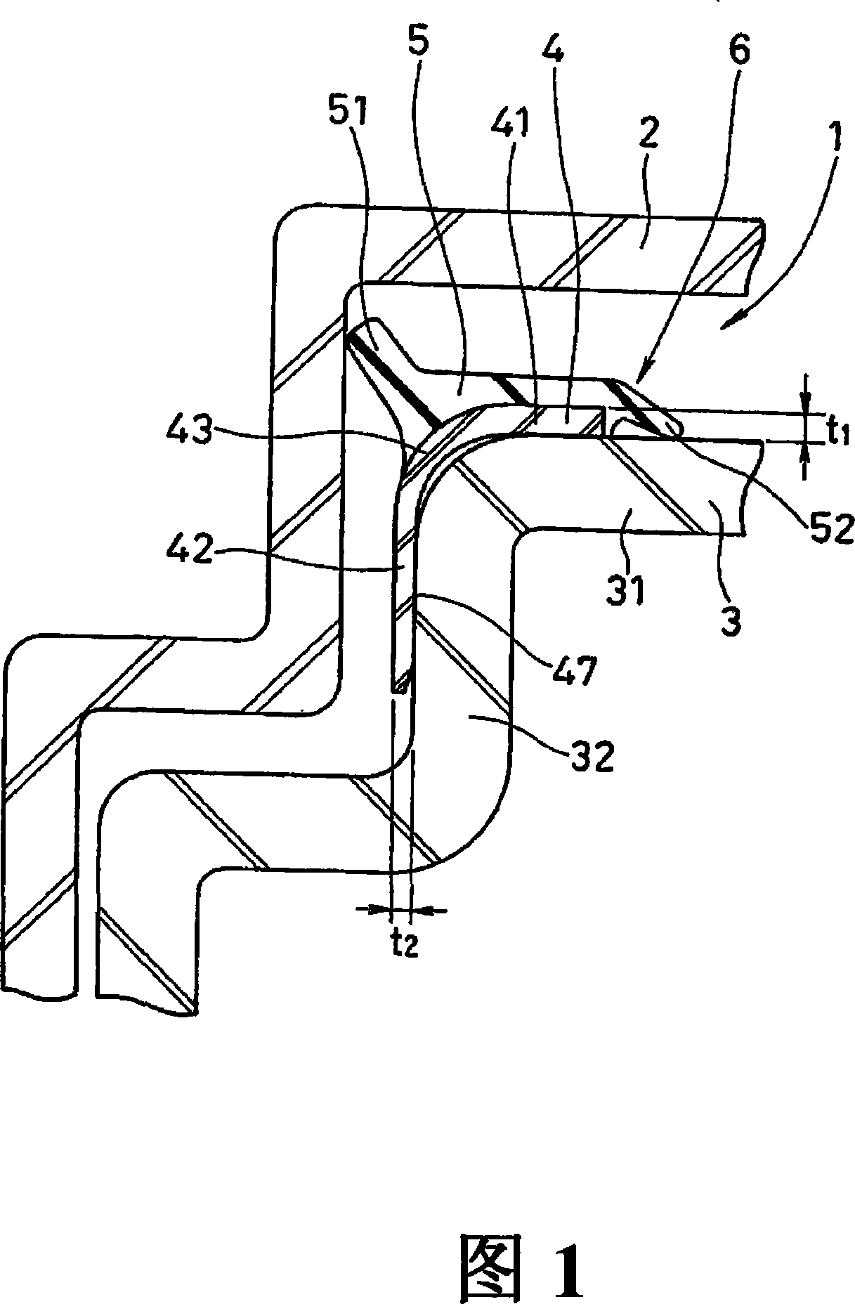
[0034] Fig. 1 is a sectional view of a main part of a sealing device according to an embodiment of the present invention to which a piston member capable of reciprocating axially in a cylinder is installed.

[0035] As shown in Figure 1, the sealing device 1 of the present invention is installed on the piston element 3 reciprocating in the axial direction in the bottomed cylindrical cylinder 2, and is used for sealing between the cylinder 2 and the piston element 3; by having a core 4 and the sealing element 6 of the sealing part 5.

[0036] The core 4 is a metal plate with an L-shaped cross-section, and is integrally formed by the following structure: the flange portion 31 located on the innermost diameter ...


PUM


Abstract

A sealing device (1) in which, even when a seal member (6) having a core metal (4) and a sealing section (5) is fitted on a piston member (3) that axially reciprocates in a bottomed circular cylinder (2), force required for the fitting can be suppressed to a low level and as a result the core metal (4) of the seal member (6) is not deformed. The wall thickness of a circular cylindrical portion (42), fitted on the piston member (3), of the core metal (4) is reduced to provide the circular cylindrical portion with spring properties. Alternately, slits (44) are equally arranged on the circumference of the circular cylindrical portion (42) of the core metal (4) or, alternatively, the circular cylinder portion (42) is constructed from claws (45).

Description

technical field [0001] The present invention relates to a sealing device which ensures sealing performance by providing a sealing element on a piston element which is controlled by oil pressure to reciprocate in a cylinder. Background technique [0002] Due to the recent multi-stage trend of automatic transmissions such as ATs and CVTs for automobiles, there is a space constraint in the axial direction in the FF type (front-wheel drive type), especially in large-capacity ATs, BPS (Bonded Piston Seal) has a large size trend. In the prior art, in order to vulcanize and bond the sealing part to the piston element, when the size of the BPS is increased, the mold for vulcanization and bonding is also increased in size, so there is a problem that the manufacturing cost increases. [0003] As a solution to this problem, Patent Document 1 below proposes to separate only the sealing portion from the piston element, and to fit the sealing element obtained by vulcanizing the sealing p...

Claims


Application Information

Patent Timeline
IPC IPC(8): F16J15/32F16D25/12F16J15/3252
CPCF16J15/061F16D25/12F16D2300/08F16J15/32
Inventor 勘崎芳行
Owner NOK CORP
Why Eureka
Try Eureka