Conveying operation method and conveying operation device

A kind of operation device and operation technology, applied in the direction of conveyor control device, feeding device, automatic control device, etc., can solve the problems of input, production efficiency reduction, workpiece movement, etc., and achieve the effect of high production efficiency

Inactive Publication Date: 2008-01-30
HONDA MOTOR CO LTD
View PDF0 Cites 16 Cited by
  • Summary
  • Abstract
  • Description
  • Claims
  • Application Information

AI Technical Summary

Problems solved by technology

[0004] However, in this conveying operation device, when the event that the trolley stops occurs during the conveyance of the workpiece, if the operation of the workpiece by the working mechanism has not been completed, the operation of the workpiece by the working mechanism is interrupted until the conveyance of the trolley. until restart
As a result, since the work in each work area of ​​the workpiece manufacturing line is interrupted, the production efficiency is significantly reduced.
[0005] In addition, in this conveying operation device, if it is limited to the case where a work mechanism such as a robot is used to perform normal work on the workpiece, the work can be efficiently performed by moving the workpiece along the conveying path, but since the workpiece is supported on the A pair of movable tables, so the workpiece cannot be moved from the transport path of the trolley to other positions, and other tasks different from normal operations, such as teaching work or work testing of operating mechanisms such as robots, must also be placed on the transport path with the workpiece in the state of
Therefore, during the period of performing other operations different from the usual ones on the workpiece, for example, other workpieces cannot be dropped into the working area of ​​the operating mechanism, and the usual operations are continued by manual work, so that the normal operations in the operating area of ​​the operating mechanism are stopped. lead to lower production efficiency

Method used


Image

  • Conveying operation method and conveying operation device
  • Conveying operation method and conveying operation device
  • Conveying operation method and conveying operation device

Examples


Embodiment Construction

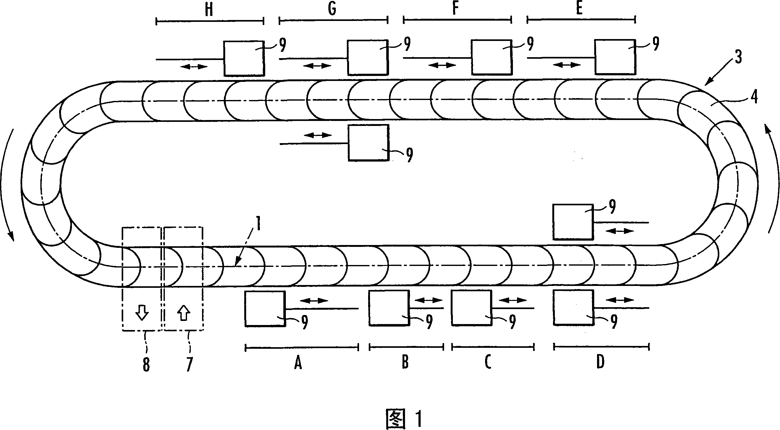
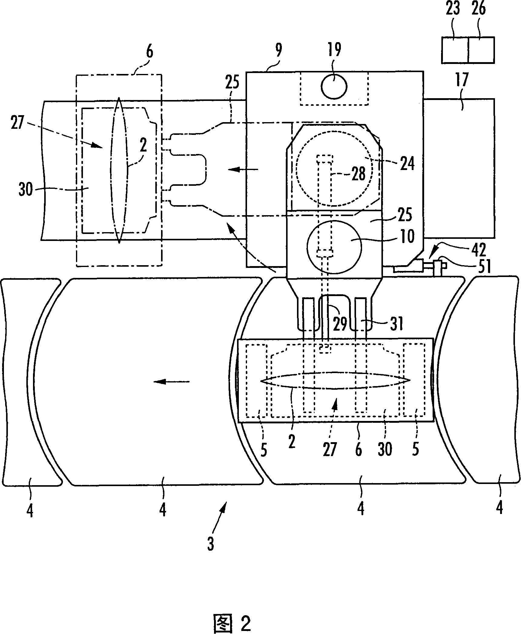
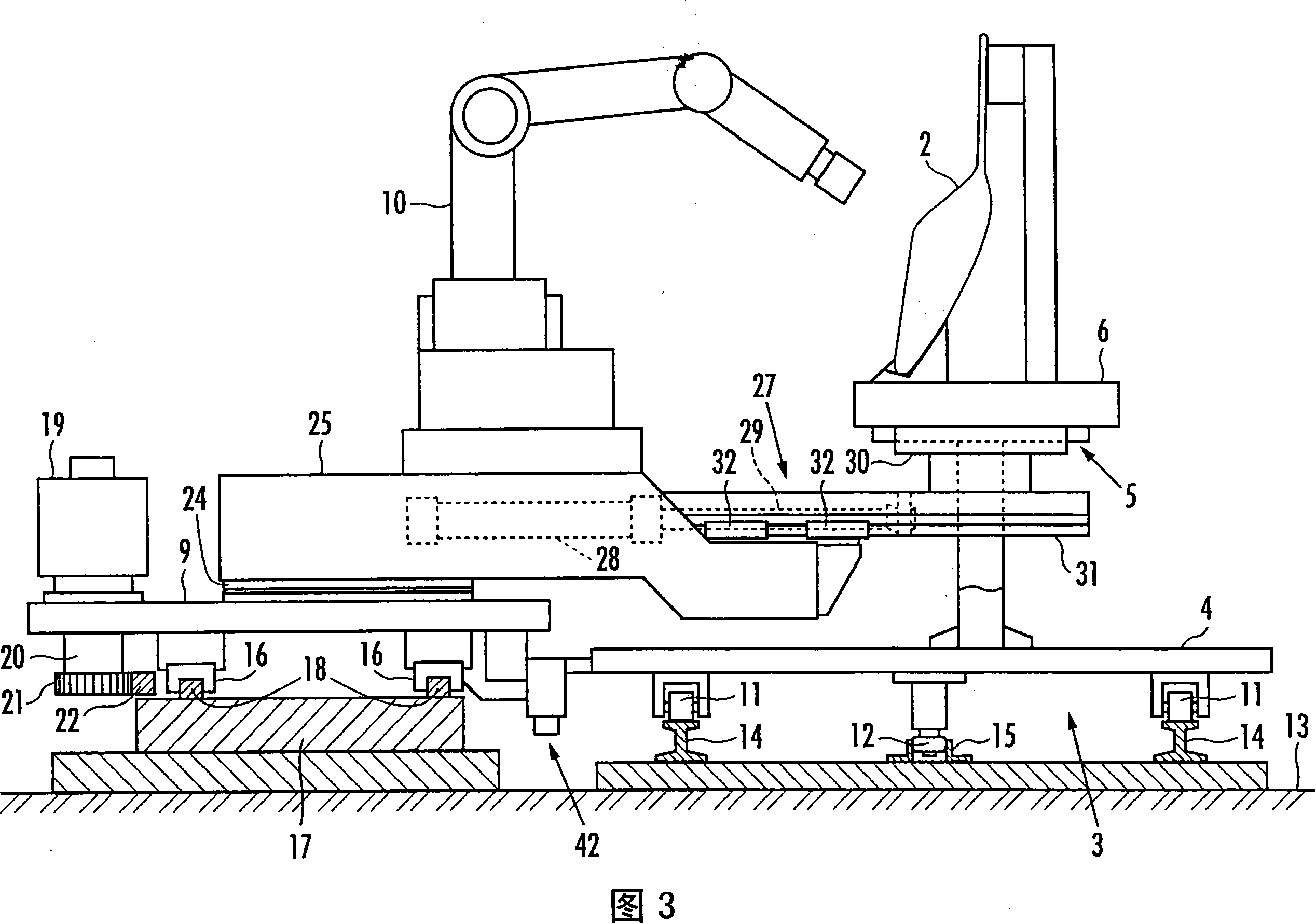
[0054] The conveying operation device of this embodiment is installed as a production line for automobile doors, and as shown in FIG. Shape workpiece conveying mechanism 3. The workpiece conveying mechanism 3 is a conveyor in which a conveying surface is formed by connecting a plurality of moving plates 4 in a ring shape, and the moving plates 4 circulate along an elliptical conveying path driven by a driving mechanism not shown. The workpiece 2 is held by the workpiece conveyance mechanism 3 with a predetermined interval therebetween. More specifically, as shown in FIGS. 2 and 3 , the workpiece 2 is held by the workpiece conveyance mechanism 3 by a plurality of workpiece holding portions 5 provided on the moving plates 4 at predetermined intervals. The workpiece 2 is held by the workpiece holding portion 5 in a state supported by the pallet 6 , and the pallet 6 is detachably held by the workpiece holding portion 5 .

[0055] Moreover, as shown in FIG. 1 , a part of the conv...


PUM


Abstract

A conveying operation method and device thereof, in which a workpiece is conveyed by a workpiece conveying mechanism (3), and a movable table (9) is moved synchronously with the conveying mechanism in the working areas (A-H) set on the conveying path (1), and the set The working mechanism on the movable table performs predetermined work on the workpiece. When the movement of the workpiece conveying mechanism (3) stops, the movable table (9) and the workpiece conveying mechanism (3) are stopped synchronously in the working area (A~H), and the specified operation on the workpiece is continued to complete a cycle of operation . When performing work other than normal work on the workpiece, the workpiece is evacuated to a position different from the conveyance path (1) while being supported on the movable table (9), and waits. As a result, when the work mechanism performs predetermined work on the workpiece while the work is being conveyed, even if the work mechanism stops conveying the workpiece, high-precision work on the workpiece can be continued, thereby suppressing a decrease in productivity.

Description

technical field [0001] The present invention relates to a transfer operation method and device for performing predetermined operations on a workpiece while transferring the workpiece. Background technique [0002] In the past, it is known that a workpiece is held on a trolley for transport as disclosed in JP-A-61-146690, and a movable table and a table equipped with operating mechanisms such as a manipulator installed along the transport path of the trolley are known. Cars move synchronously and carry out predetermined operations on workpieces being conveyed. In this device, a pair of movable tables are arranged on both sides of the conveying path of the trolley. When the two movable tables move synchronously with the trolley, based on the receiving devices respectively provided by the two movable tables, the two movable tables Receive and support both sides of the workpiece, and move the workpiece to the original pallet after the work by each working mechanism is completed...

Claims


Application Information

Patent Timeline
Patent Type & Authority Applications(China)
IPC IPC(8): B23Q7/14B23Q15/00B65G35/00B65G43/00
Inventor 野口纯男山室英哉高桥贡安达正和
Owner HONDA MOTOR CO LTD
Why Eureka
Try Eureka