Device and method for pumping and filtering air containing dust and/or fibre on the spinning machine

A technology for textile machines and equipment, applied in the field of equipment and methods for suctioning and filtering air containing dust and/or fibers on textile machines, capable of solving problems such as increased energy consumption

Inactive Publication Date: 2008-01-30
MASCHINENFABRIK RIETER AG
View PDF4 Cites 23 Cited by
  • Summary
  • Abstract
  • Description
  • Claims
  • Application Information

AI Technical Summary

Problems solved by technology

Reduced suction action of the suction device, for example due to severe filter coating, can be compensated accordingly by increasing the motor power, however, this leads to increased energy consumption and may require a higher performance motor

Method used


Image

  • Device and method for pumping and filtering air containing dust and/or fibre on the spinning machine
  • Device and method for pumping and filtering air containing dust and/or fibre on the spinning machine
  • Device and method for pumping and filtering air containing dust and/or fibre on the spinning machine

Examples


Embodiment Construction

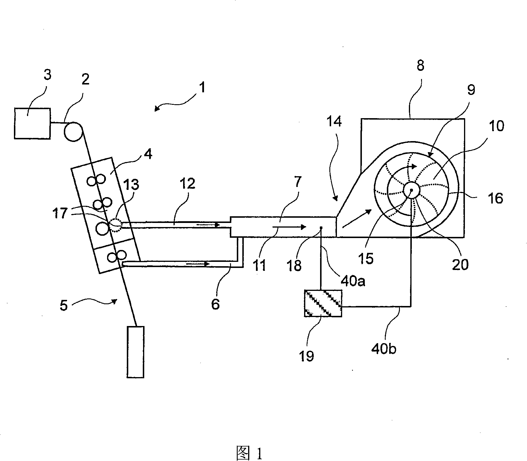
[0066] In FIG. 1 , a suction and filter device 14 follows the textile machine 1 , in particular the spinning machine, and is shown here only schematically. In this figure, the yarn 2 is conveyed from the roving bobbin 3 to the drafting device 4 with the pneumatic compacting unit 13, where it is drafted, compacted and then conveyed to the spinning station 5 in particular is on the spindle. A suction line 6 is provided between the drafting device 4 and the collecting unit 13 , which leads to the channel 7 . The suction at the collecting unit 13 is generated by the suction duct 12 which also leads to the channel 7 . The flow direction of the extracted air to be filtered is indicated by arrow 11 .

[0067] At least one suction pipe 6 and / or one suction pipe 12 is arranged at each spinning station 5 or between each spinning station 5 and the drafting device 4, wherein a plurality of pipes can pass through To a common channel 7 or multiple channels 7. The suction pipes 6 , 12 ar...


PUM


Abstract

The device for the suction and filtration of dust- and/or fiber loaded air on spinning machines (1), comprises working places consisting of a suction channel (7), a filtering device (8) with a filter forming a filtering surface (16), a system for removing the filter outflow from the filtering surface, a vacuum source (10) for generating an induced draft, an operating means for carrying out a filter cleaning process using a removal system, and a vacuum sensor arranged in the main suction channel for measuring the vacuum in a vacuum zone before and/or after the filtering. The device for the suction and filtration of dust- and/or fiber loaded air on spinning machines (1), comprises working places consisting of a suction channel (7), a filtering device (8) with a filter forming a filtering surface (16), a system for removing the filter outflow from the filtering surface, a vacuum source (10) for generating an induced draft, an operating means for carrying out a filter cleaning process by a removal system, and a vacuum sensor arranged in the main suction channel for measuring the vacuum in a vacuum zone before and/or after the filtering. The device contains a controller or regulator for vacuum in the vacuum zone before and/or after the filtering surface based on the vacuum values, vacuum target values or vacuum target value areas, which are measured by the vacuum sensor. The controller or regulator is connected with a driving mechanism for filter cleaning. The controlling or regulating of the vacuum takes places by the operation of the driving mechanism. The spinning place contains suction places (17), over which polluted air is sucked out and supplied over a central suction channel or -channel of the filter arrangement. The vacuum source contains an axial- or radial ventilator. The filter outflow is liftable or removable from the filtering surface using removal- or a lifting device and is fed to a collecting- or disposing device. The controller contains a signal converter and a control device, by which the measured values received by the vacuum sensor in the form of vacuum values are compared with the vacuum target values and vacuum target value areas. Controlling or regulating signals are generated for correcting the variation of actual value from the target value for operating on an actuator and/or a final control element containing driving means. The filtering device contains a filter drum with a cylinder shaped, fixed or flexible filter surface, which is arranged on the removal system. The driving mechanism comprises a drive system for turning the filter drum around the drum axis. The filter cleaning is carried out by a continuous or sequential turning of the filter drum, by which the filter surface is directed to the removal device and the filter outflow is removed. The driving mechanism contains a hydraulic or pneumatic piston drive, and a linear motor or electric cylinder, which is connected with a gear between the driving mechanism and the filter. A control is intended for thread count and/or equipment parameters of the pressure ratio in the channels and/or pipes are adjustable. The control consists of a means for changing the vacuum over the filter device and/or over the ventilator output. The filter device contains a continuous filter band forming a space, and electro motor driving mechanism for a circulatory movement of the filter band, which forms a layered filter surface. Independent claims are included for: (1) a spinning machine; and (2) a method for the suction and filtration of dust- and/or fiber loaded air on spinning machines.

Description

technical field [0001] The invention relates to a device for suctioning and filtering air containing dust and / or fibers on a textile machine with one or more stations, the device comprising a suction channel, a filter with a filter surface The filter device, the removal device for removing filter waste from the filter surface, the vacuum source for generating suction, and the drive device for carrying out the filter cleaning process by means of the removal device, also includes at least one device for measuring Vacuum sensor for the vacuum level in the vacuum area upstream and / or downstream of the filter. Furthermore, the invention relates to a method for controlling / regulating the vacuum level in a suction system. Background technique [0002] It is known to remove impurities, such as loose or flying fibers (man-made fibres, microfibres, cotton fibers or the like) and dust on textile machines, by means of suction devices, wherein these impurities are Especially due to the...

Claims


Application Information

Patent Timeline
Patent Type & Authority Applications(China)
IPC IPC(8): D01H11/00D01H5/66D01G15/76D01G19/28B01D33/00B01D35/00
CPCD01H11/005B01D2273/28B01D46/24B01D46/0065B01D46/0056D01H11/00B01D46/682B01D46/681
Inventor 伊日·梅杜纳彼得·什克瓦日尔埃米尔·克雷茨马丁·迪本多费尔马库斯·米勒
Owner MASCHINENFABRIK RIETER AG
Why Eureka
Try Eureka