Reduction pot setup method in stove and reducing furnace constructed by the method

A reduction tank and reduction furnace technology are applied in the metal vacuum smelting reduction furnace, and the metal vacuum smelting reduction tank is installed in the reduction furnace, which can solve the problems of insufficient heat utilization, large deformation of the reduction tank, inconvenient feeding, etc. The effect of improving heat utilization rate, improving production efficiency and prolonging service life

Inactive Publication Date: 2008-01-30
GUIZHOU SHIJI TIANYUAN MINING IND
View PDF0 Cites 0 Cited by
  • Summary
  • Abstract
  • Description
  • Claims
  • Application Information

AI Technical Summary

Problems solved by technology

Solve the inconvenience of feeding the existing reduction tank, the amount of feeding is small, a

Method used


Image

  • Reduction pot setup method in stove and reducing furnace constructed by the method

Examples


Embodiment

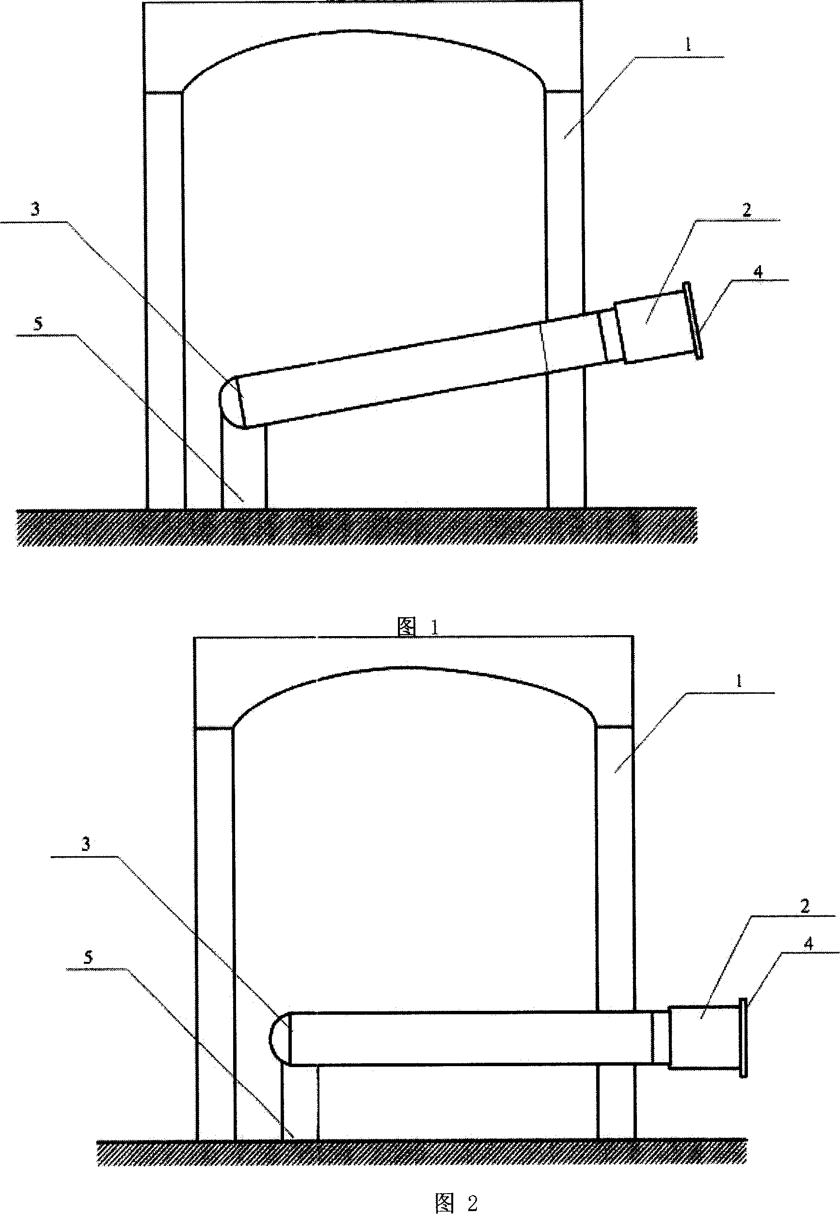
[0011] Embodiment: The following is an example of an inclination angle of 10° to illustrate a specific implementation.

[0012] The installation method of the metal vacuum smelting reduction tank in the furnace is that the closed end of the reduction tank faces downwards, and the opening end of the reduction tank faces upwards, and is installed obliquely in the reduction furnace kiln body. A metal vacuum smelting reduction furnace constructed by this method is shown in Figure 1, with the closed end of the reduction tank facing down and the open end facing up, and placed in the reduction furnace kiln body 1 at an inclination angle of 10°; the reduction tank 3 The open end of the kiln is supported by the reduction furnace kiln body 1, and the closed end is supported by the support 5 built in the reduction furnace. The crystallizer 2 is connected with the reduction tank 3, and the crystallizer 2 is fed into the reduction tank 3. After the feeding is completed, the The feed port e...


PUM


Abstract

The invention discloses a setting method of a metal vacuum-smelting reduction pot in a reduction furnace and a reduction furnace constructed by using the method. The sealing end of the reduction pot downwards and the material inlet of the reduction pot upwards are tipsily positioned in the reduction furnace. The sealing end of a reduction pot (3) is supported on a support saddle (5) arranged in a reduction furnace kiln body (1). The material inlet of the reduction pot (3) is supported on a position which is higher than the support saddle (5) on the reduction furnace kiln body (1). A crystallizer (2), which is connected with the material inlet of the reduction pot, is positioned outside the reduction furnace kiln body (1). The angle between the reduction pot (3) and a horizontal plane is 3-30 degrees. The invention solves the problems of inconvenience of adding materials of the existing reduction pot, small feeding amount, and great labor intensity when workers add materials, large deformation of the reduction pot and deficiency in energy utilization.

Description

technical field [0001] The invention relates to a metal vacuum smelting reduction furnace, in particular to a method for setting a metal vacuum smelting reduction tank in the reduction furnace and a reduction furnace constructed by the method. Background technique [0002] The structure of metal vacuum smelting reduction furnace is composed of reduction tank, crystallizer and reduction furnace kiln body. The existing reduction tank is supported by the kiln body and the support in the kiln body. In addition, the material is fed into the reduction tank from the mouth of the crystallizer, and the other end is closed, as shown in Figure 2. The existing setting method is very inconvenient when feeding materials into the reduction tank. There is a problem that the amount of material fed into the reduction tank is too small, and the labor intensity of the workers is high; It is also under high temperature, and due to the force of slag removal, the deformation of the reduction tank...

Claims


Application Information

Patent Timeline
IPC IPC(8): F27B14/08F27B14/00
Inventor 张继强奉建湘
Owner GUIZHOU SHIJI TIANYUAN MINING IND
Why Eureka
Try Eureka