
Image-forming spectral measurement device

A measurement device and imaging spectrum technology, which is applied in the direction of measurement device, optical radiation measurement, spectrometry/spectrophotometry/monochromator, etc., can solve the problems of large error in measurement results, etc., and meet the requirements of improving accuracy and working conditions Effect of low and high measurement accuracy

Inactive Publication Date: 2008-01-30
XI'AN INST OF OPTICS & FINE MECHANICS - CHINESE ACAD OF SCI
View PDF0 Cites 3 Cited by
  • Summary
  • Abstract
  • Description
  • Claims
  • Application Information

AI Technical Summary

Problems solved by technology

[0003] The purpose of the present invention is to provide an imaging spectrum measurement device, which solves the technical problems of large measurement results caused by atmospheric vibration and atmospheric scattering in the background technology

Method used


Image

  • Image-forming spectral measurement device

Examples


Embodiment Construction

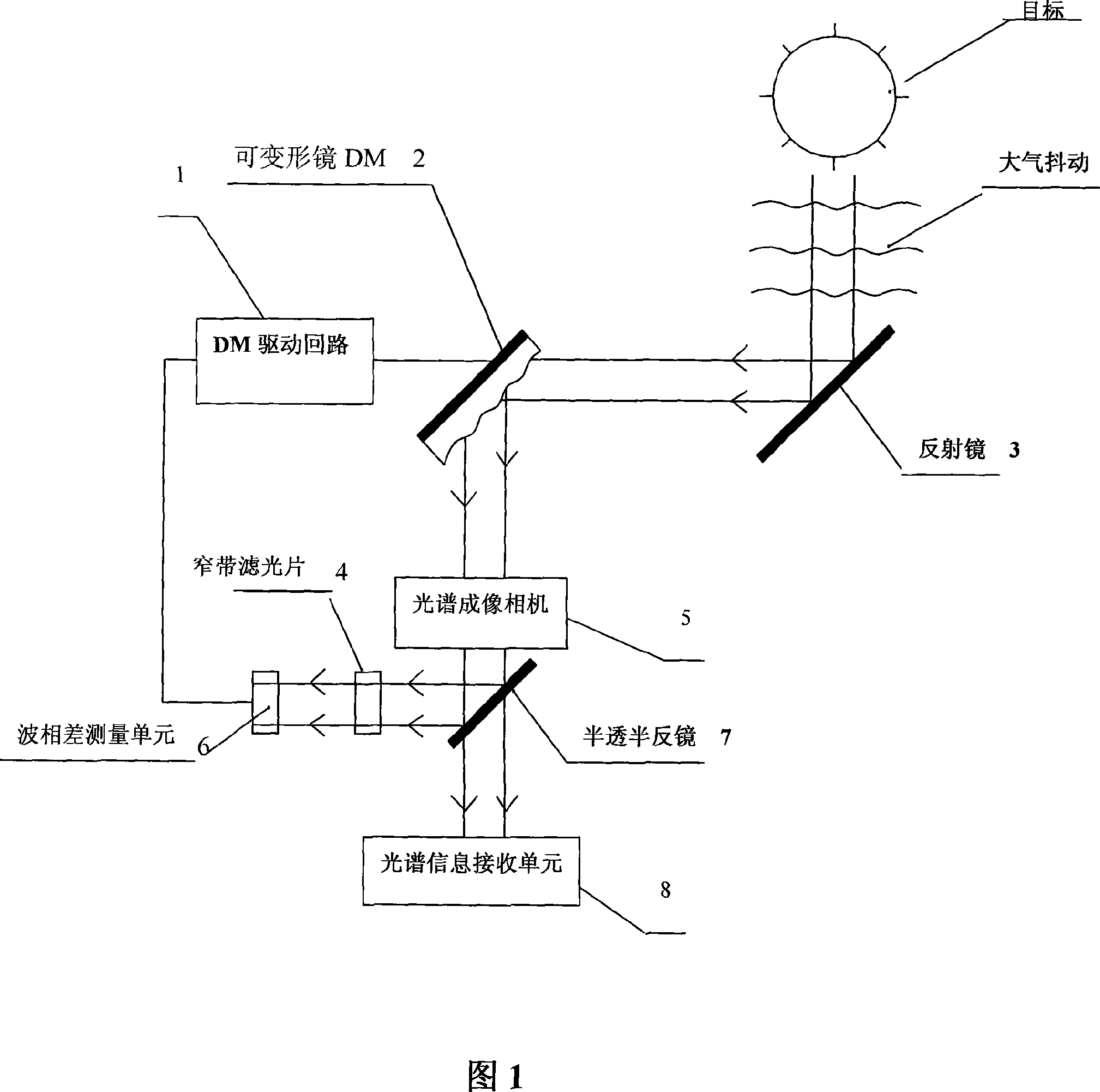
[0020] Referring to Fig. 1, the present invention comprises spectral imaging camera 5, the optical path measurement compensation device that is connected with spectral imaging camera 5, and this optical path measurement compensation device comprises reflection mirror 3 and deformable mirror DM2 (Deformable mirror), deformable mirror DM2 is arranged on spectral On the incident light path of the imaging camera 5, the mirror 3 is arranged on the incident light path of the deformable mirror DM2. By adjusting the deformable mirror DM2, the compensation of the optical path difference in the light path can be realized, thereby eliminating the error of measuring the target spectrum and improving the spectrum. The accuracy of the measurement. The optical path measurement compensation device also includes a DM drive circuit 1, a wave phase difference measurement unit 6, a narrow band filter 4 and a half mirror 7, the deformable mirror DM2 is connected with the wave phase difference measu...


PUM


Abstract

The invention relates to an imaging spectrum measuring device, in particular to the imaging spectrum measuring device detecting a space target. The technic proposal of the invention is that: the invention is the imaging spectrum measuring device, the device comprises a spectrum imaging camera and an optical path measuring compensating device connected with the spectrum imaging camera, the optical path measuring compensating device comprises a reflector and a deformable mirror DM, the deformable mirror DM is arranged on an incidence optical path of the spectrum imaging camera, the reflector is arranged on the incidence optical path of the deformable mirror DM. the invention aims at providing the imaging spectrum measuring device and solving the technical problems of bigger errors of the measuring caused by the atmospheric dithering and the atmospheric scattering, etc. in the background technology.

Description

technical field [0001] The invention relates to an imaging spectrum measurement device, in particular to an imaging spectrum measurement device for detecting space targets. Background technique [0002] In the detection and reconnaissance of space targets, it is necessary to measure the spectral information of the target with a spectral imaging camera. However, when the existing spectral imaging cameras are directly applied to space targets, the wave fronts of light waves are distorted due to the effects of atmospheric jitter and atmospheric scattering, and there are large errors in the measured target spectral information. And in the process of using the spectral imaging camera, the measurement error caused by the camera itself due to production reasons such as manufacturing and assembly is often ignored. The errors formed in the above measurement process are difficult to simulate with the current calculation model, and cannot be repaired by software methods. Contents of...

Claims


Application Information

Patent Timeline
Patent Type & Authority Applications(China)
IPC IPC(8): G01J3/28G01J3/02
Inventor 相里斌李霞赵建科袁艳
Owner XI'AN INST OF OPTICS & FINE MECHANICS - CHINESE ACAD OF SCI
Learn More