Fuel filter system

A filter system and fuel technology, applied in the direction of charging system, filter separation, filter circuit, etc., can solve the problems of loss of coalescing filter performance, deterioration of water separation performance, flow resistance and other problems

Inactive Publication Date: 2008-01-30
MANN HUMMEL GMBH
View PDF1 Cites 9 Cited by
  • Summary
  • Abstract
  • Description
  • Claims
  • Application Information

AI Technical Summary

Problems solved by technology

The disadvantage of this construction is that the main filter element is loaded with dirt due to its effective filtering properties and this dirt reduces or prevents the flow through.
Furthermore, over time, the main filter element loses its performance as a coalescing filter, which means that the filter system as a whole loses its water separation performance or this water separation performance deteriorates until replacement The filter element

Method used


Image

  • Fuel filter system
  • Fuel filter system
  • Fuel filter system

Examples


Embodiment Construction

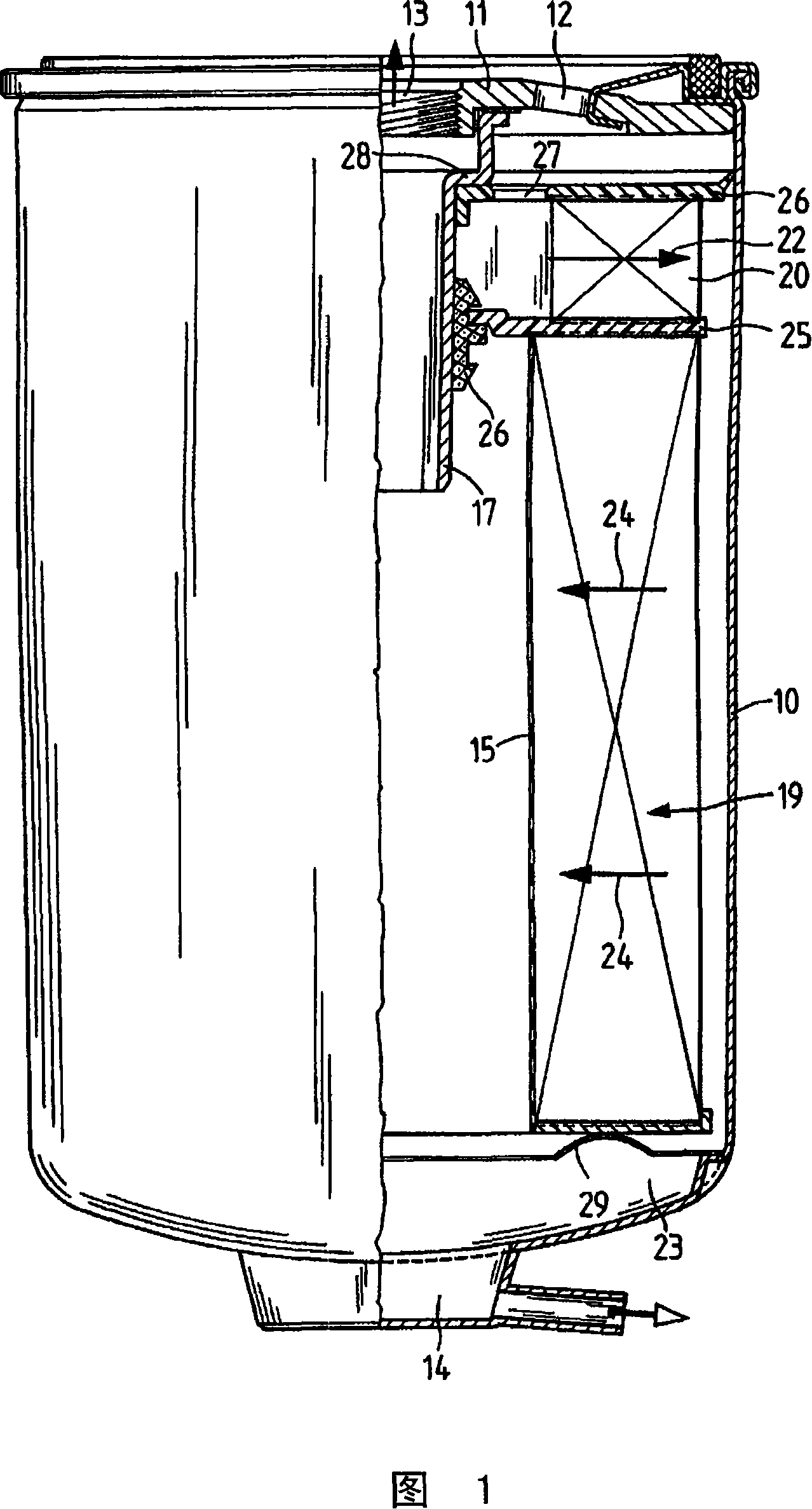
[0016] The fuel filter according to FIG. 1 includes a housing 10 . The housing 10 is substantially pot-shaped. The housing is closed in the upper region by a cover 11 which has openings 12 for the inflow of fuel, one of which is shown here. The inlets are arranged as perforations on a partial circle and are evenly spaced. Furthermore, an outlet 13 is provided, from which cleaned fuel can be removed. At the lower end of the housing 10 there is a drain valve 14 , which is only schematically shown here. Inside the housing there is a standpipe 17 . In the housing 10 there is a particle filter 19 which is made of a zigzag-folded filter material, which can have a multi-layer structure, for example. A coalescing element 20 is arranged above the particle filter 19 . In the exemplary embodiment shown, this condensation element 20 is likewise produced from a zigzag folded medium. This medium may be a polyester material, polyamide or other material with condensation properties for ...


PUM


Abstract

The invention relates to a fuel filter provided with a coalescing element (20). The coalescing element serves to improve the separation effect of the water droplets and is arranged in the immediate inlet region of the fuel. The fuel filter is distinguished by its simple construction. The coalescing element therefore has an upper end gasket (26) which extends as far as the inner wall of the housing (10) and thus not only seals the coalescing element but also simultaneously Seal the inflow area and the bulk solution area outside. The coalescing element (20) and the particle filter (19) are arranged on a common partition (25). This spacer is supported by a profiled seal on a standpipe (17) arranged in the middle of the fuel filter. The end gaskets of the coalescing element can be produced with two-component injection molding technology or also with plastics technology with profiled seals molded from elastomeric materials.

Description

technical field [0001] The invention relates to a filter system for fuel, in particular a diesel filter, according to the preamble of independent claim 1, wherein a particle filter is arranged in the housing. Background technique [0002] A fuel filter is known from US 5,084,170. The fuel filter has a housing in which a main filter element and a second filter element are arranged. Fuel flows through the primary filter element from the inside out. Furthermore, this main filter element has coalescing properties, so that water that may be present in the fuel coalesces, ie forms larger water droplets. These water droplets enter a water accumulation chamber. In order that water droplets do not flow through the second filter element, the filter element is provided with a hydrophobic material, in particular silicon, so that an external water barrier is formed. Both the first filter element and the second filter element are produced from a pleated filter paper or filter fiber we...

Claims


Application Information

Patent Timeline
Patent Type & Authority Applications(China)
IPC IPC(8): B01D36/00
CPCB01D36/003B01D27/148F02M37/24
Inventor G·-M·克莱因G·约克沙斯M·克莱因
Owner MANN HUMMEL GMBH
Why Eureka
Try Eureka