Erection method of large-span continuous steel truss arch

A large-span, steel truss technology, applied in the erection/assembly of bridges, bridge construction, bridges, etc., can solve problems such as large reaction force of supports, inability to meet stress requirements, and difficulty in realization.

Active Publication Date: 2008-02-06
CHINA RAILWAY MAJOR BRIDGE ENG GRP CO LTD
View PDF0 Cites 35 Cited by
  • Summary
  • Abstract
  • Description
  • Claims
  • Application Information

AI Technical Summary

Problems solved by technology

In the past, the method of assisting cantilever construction by setting up a single-layer sling tower can no longer meet the stress requirements in the cons...

Method used


Image

  • Erection method of large-span continuous steel truss arch
  • Erection method of large-span continuous steel truss arch
  • Erection method of large-span continuous steel truss arch

Examples


Embodiment Construction

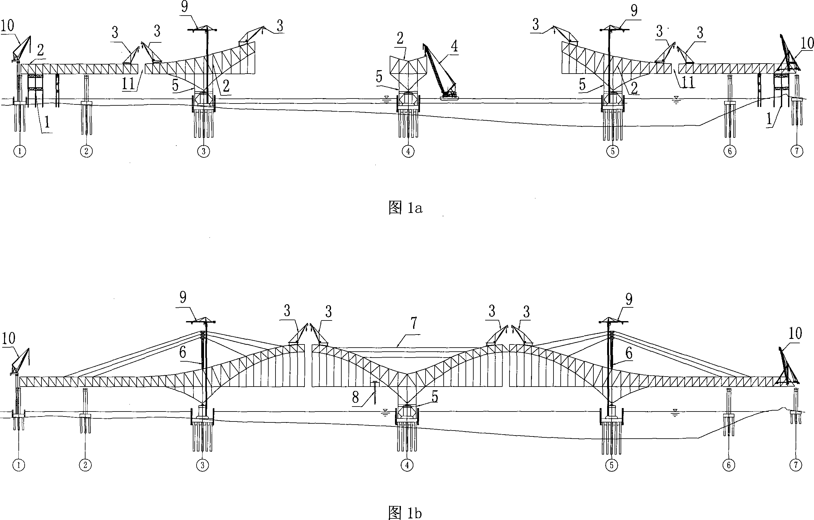
[0033] The construction method of the long-span continuous steel truss arch is mainly composed of: side span steel truss girder installation, pier side bracket 5 installation, sling tower 6, main span steel truss arch installation, and closing.

[0034] 1. Installation of side span steel truss girders

[0035] The installation of the steel truss starts from pier ①, install the initial internode steel truss 2 on the temporary support pier 1 from pier ① to pier ②, and assemble the girder crane 3 on the steel truss that has been erected. The machine 3 starts to erect the beam toward the pier ② direction. After the erection reaches the top of the pier ②, it is fully cantilevered and installed until the steel truss between the pier ② and the pier ③ closes the dragon mouth 11. A steel truss member lifting station 10 is set beside the pier ①, which is responsible for loading and supplying the rod members for cantilever installation.

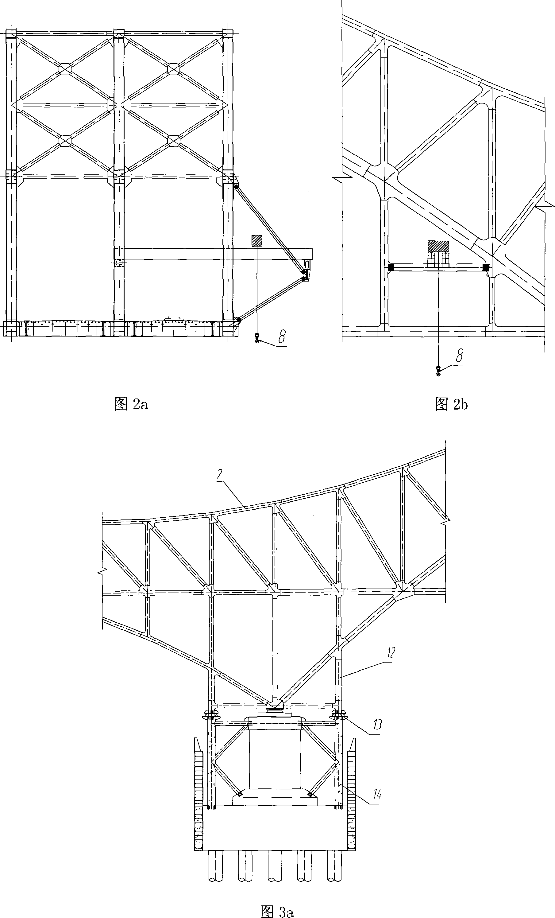
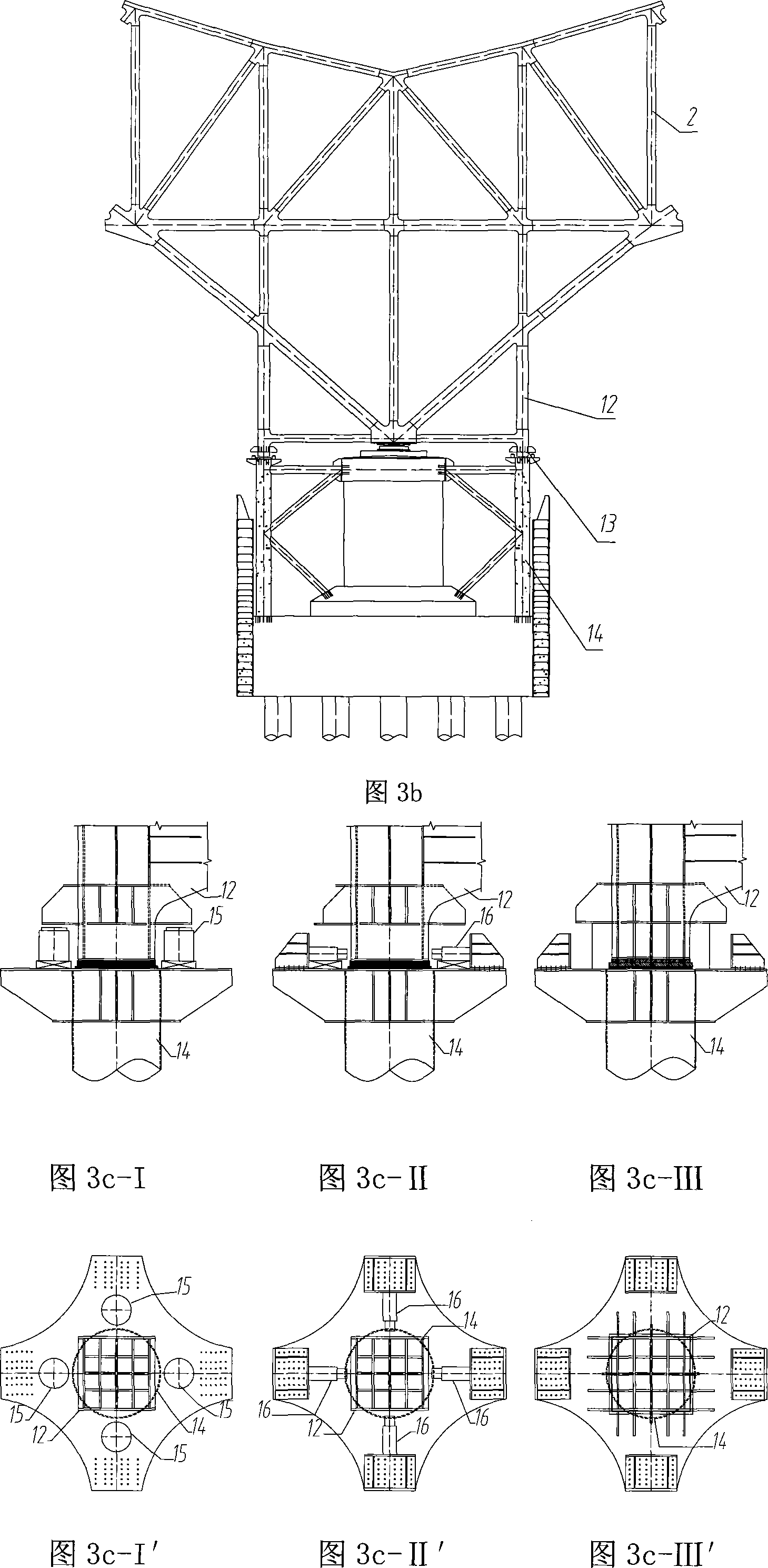
[0036] 2. Bracket beside the pier

[0037] The...


PUM


Abstract

An erection method of a large-span continuous steel truss arch, in the construction of a large-span continuous truss arch bridge, a bridge pier is taken as the foundation, a bracket beside the pier is arranged, a plurality of steel trusses with an interval on the top pier are arranged on the bracket beside the pier, and a double-suspension erection system is formed. A full-rotation beam erection lifting machine is positioned at the truss of the pier top, and truss bar is arranged one by one. After the suspension arm reaches a certain degree, a horizontal rope or a multi-layer tower with a suspended cable and a stay cable is arranged to maintain the double-suspension arm to extend forwards until closure.

Description

technical field [0001] The invention relates to a method for erecting a steel truss arch of a bridge. Specifically, the pier body of the bridge is used as the foundation, the pier side brackets are set, and several internode steel trusses on the top of the pier are installed on the pier side brackets to form a double cantilever erection system. Install a full-slewing girder crane on the trusses at the top of the pier, and install trusses one by one. After the cantilever reaches a certain level, set horizontal cables or multi-layer sling towers and stay cables to maintain the double cantilever system and continue to extend forward until closing. Background technique [0002] When the traditional steel truss arch is erected by cantilever, a single-layer sling tower is generally installed at each arch foot to assist the steel truss cantilever construction, so as to adjust the internal force and displacement during the construction of the steel truss arch, and finally through t...

Claims


Application Information

Patent Timeline
IPC IPC(8): E01D21/00E01D21/10E01D21/06
CPCE01D21/00
Inventor 秦顺全周外男潘东发李军堂涂满明毛伟琦马涛王东辉龚国锋覃勇刚
Owner CHINA RAILWAY MAJOR BRIDGE ENG GRP CO LTD
Why Eureka
Try Eureka