
Wind tunnel type electricity generator

A technology of generators and wind tunnels, which is applied in wind power generation, wind engines, wind motor combinations, etc., can solve the problems of not being able to block the wind, single function, etc., and achieve the effects of improving power generation efficiency, wind energy efficiency, and reasonable structural design

Inactive Publication Date: 2008-02-06
戚永维
View PDF3 Cites 13 Cited by
  • Summary
  • Abstract
  • Description
  • Claims
  • Application Information

AI Technical Summary

Problems solved by technology

The above two comparison documents both solve the problem of the amount of air gathering, and cannot block the wind when the wind speed is super strong, and the functions are relatively simple.
Most of the existing power generation devices drive the generator rotor to rotate through the transmission shaft, and there is no report about the hollow rotor and the impeller directly driving the rotor to rotate

Method used


Image

  • Wind tunnel type electricity generator
  • Wind tunnel type electricity generator

Examples


Embodiment Construction

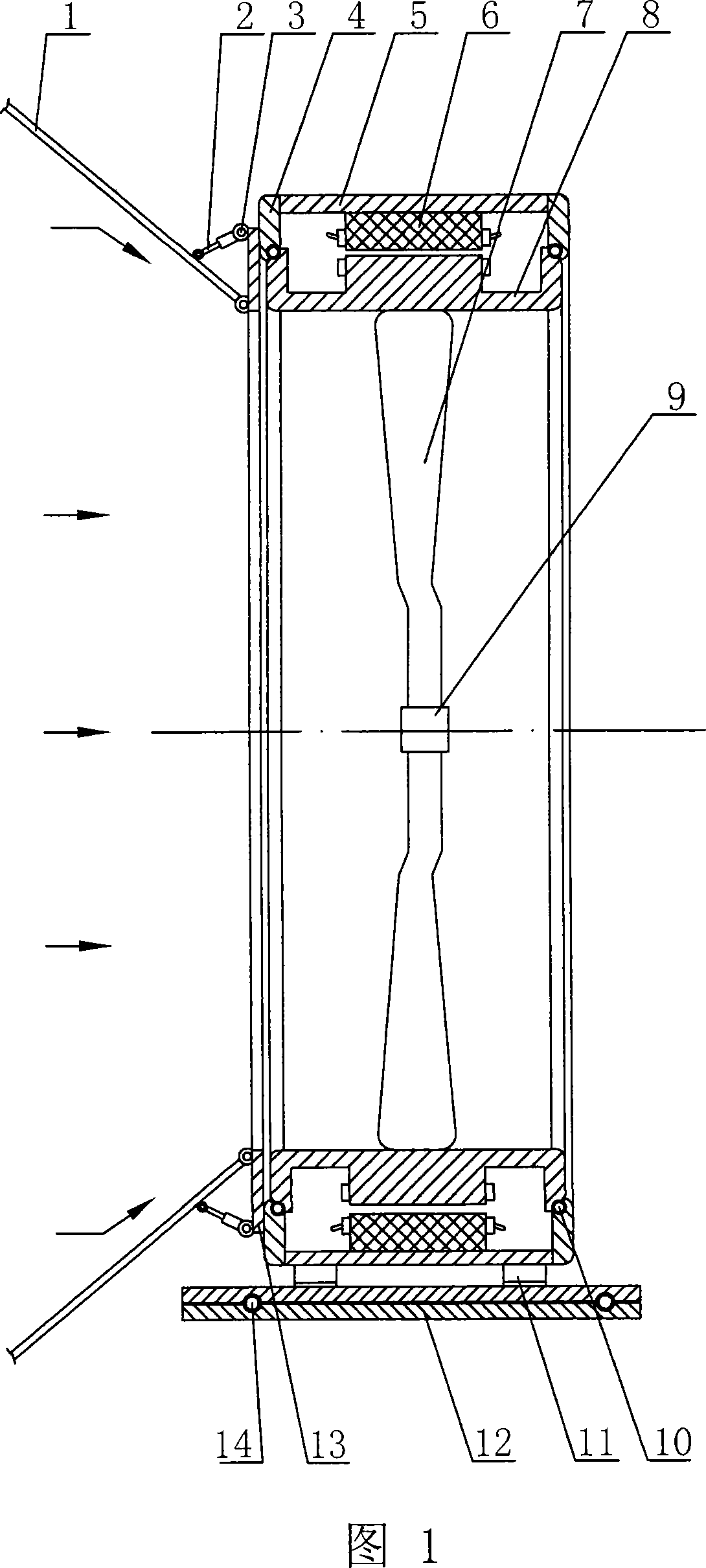
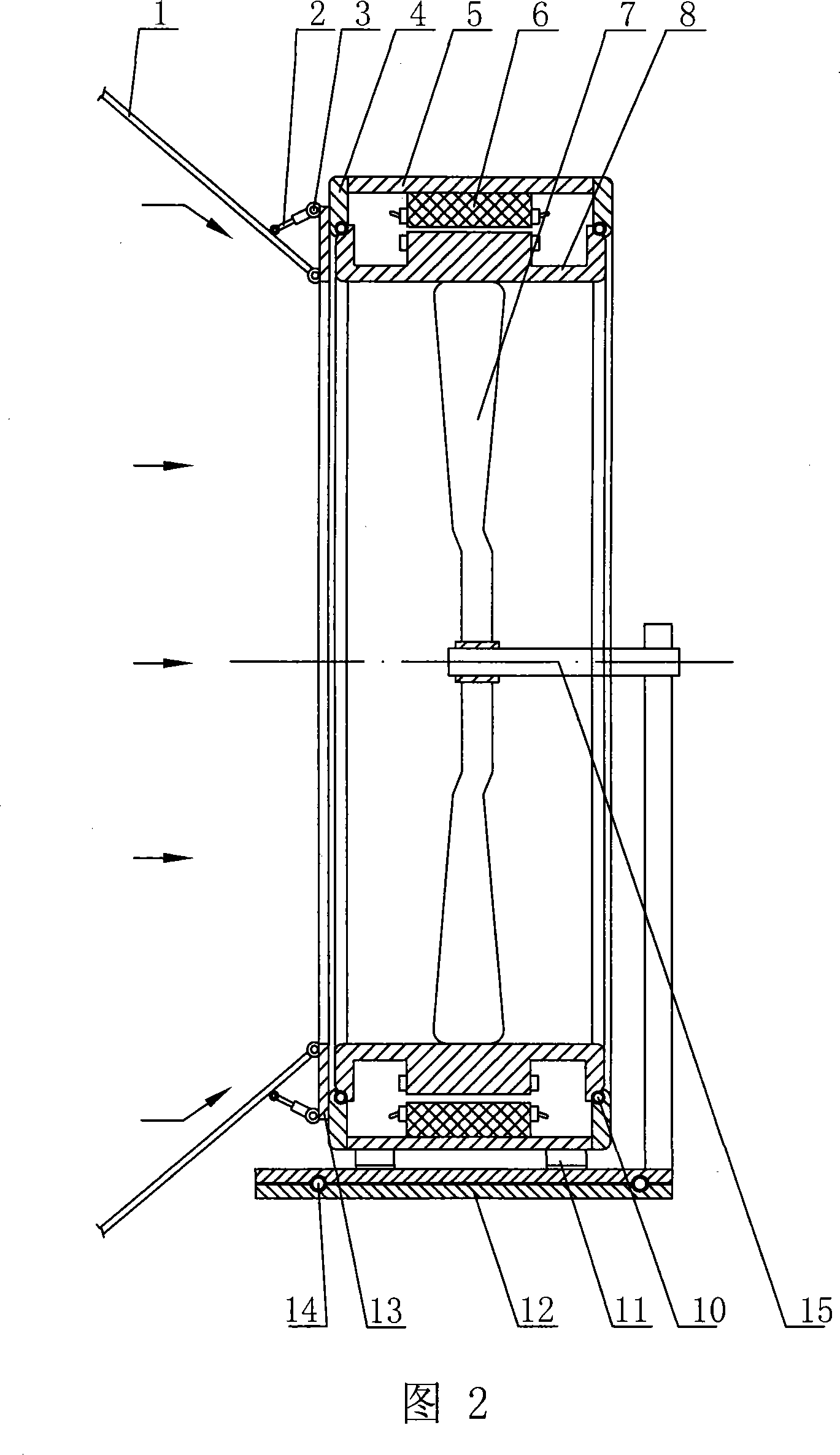
[0011] The specific structure of the present invention will be described in detail according to Fig. 1-2. The wind tunnel type wind generator can be made into a type I structure (as shown in Figure 1) or a type II structure (as shown in Figure 2) according to design requirements. It mainly includes an adjustable windshield, a casing 5, a stator 6, a rotor 8, blades 7, a turntable base 12 and the like. Wherein the casing 5 with the adjustable windshield utilizes the support 11 thereon to be fixed on the turntable type base 12 . The turntable base 12 has a built-in direction adjustment motor (not shown in the figure). The basic technical parameters of the casing 5 and the stator 6, rotor 8 and blades 7 assembled therein, as well as the specification and quantity of the blades 7 used, should be determined with reference to the specification requirements of the existing generator and according to actual use needs. Appropriately changing the shape of the blades 7 can make the dev...


PUM


Abstract

The present invention relates to a wind tunnel typed motor which uses acting force of wind, steam, and current to drive the lamina to directly rotate the rotor, the motor comprises a shell with an adjustable fan housing which is fixed on a rotating-disk base, a stator, a rotor, and a lamina in the motor. The technical points are that the inner annulus of the stator is fixed and connected with the top of the lamina. The rotor is arranged in the stator by a bearing and causes the slide of the outer annulus of the rotor to rotate along the parallels on a shoe plate at the two sides of the shell. The adjustable fan housing consists of a verge board which is hinged at the periphery of a junction panel, and the junction panel is fixed at the lateral of the shoe plate of the shell. The cylinder body end of a fluid cylinder is hinged on the junction panel by a pin roll, and the piston head of the fluid cylinder is hinged on a verge board. The fluid cylinder drives the verge board to swing around an articulated axle. The rational structure of the motor obviously improves the capacity of generating electricity, which can gather wind in when the speed of wind is rather slow, strengthen the wind energy efficacy, block wind in strong wind, effectively prevent components from damage,, and ensure the safe operation.

Description

technical field [0001] The invention relates to a power generation device, in particular to a wind tunnel generator which uses the force of wind, steam and water flow to drive blades to directly drive the rotor to rotate. It is suitable for various power generation places. Background technique [0002] At present, most of the generators widely used are traditional steam turbine generators, hydro generators, wind turbine generators, diesel generators, etc. Most of the traditional structures use the drive shaft to drive the generator rotor to rotate. The drive shaft is limited by factors such as its own weight and the size of the supporting bearings. It is not suitable to manufacture particularly large structural parts. Therefore, it is impossible to make the generator rotor and stator super large. , so the improvement of this kind of power generation device has become the object of people's general research. The inventor once designed a kind of wind power generation device (...

Claims


Application Information

Patent Timeline
Patent Type & Authority Applications(China)
IPC IPC(8): F03D9/00F03D1/06F03D1/04
CPCY02E10/725F05B2220/7066F05B2240/13H02K7/183F03D1/04Y02E10/721F03D13/10Y02E10/72
Inventor 戚永维
Owner 戚永维
Learn More