Vibration dynamometer

A dynamometer and vibrator technology, applied in vibration massage, sports accessories, passive exercise equipment, etc., can solve the problem of not allowing the overall training concept, and achieve the effect of compact design and weight reduction

Inactive Publication Date: 2008-02-13
D·考尔兹
View PDF6 Cites 3 Cited by
  • Summary
  • Abstract
  • Description
  • Claims
  • Application Information

AI Technical Summary

Problems solved by technology

MVT products of the prior art are suitable only for selected parts of the training therapy, these devices do not allow for a holistic training concept

Method used


Image

  • Vibration dynamometer
  • Vibration dynamometer
  • Vibration dynamometer

Examples


Embodiment Construction

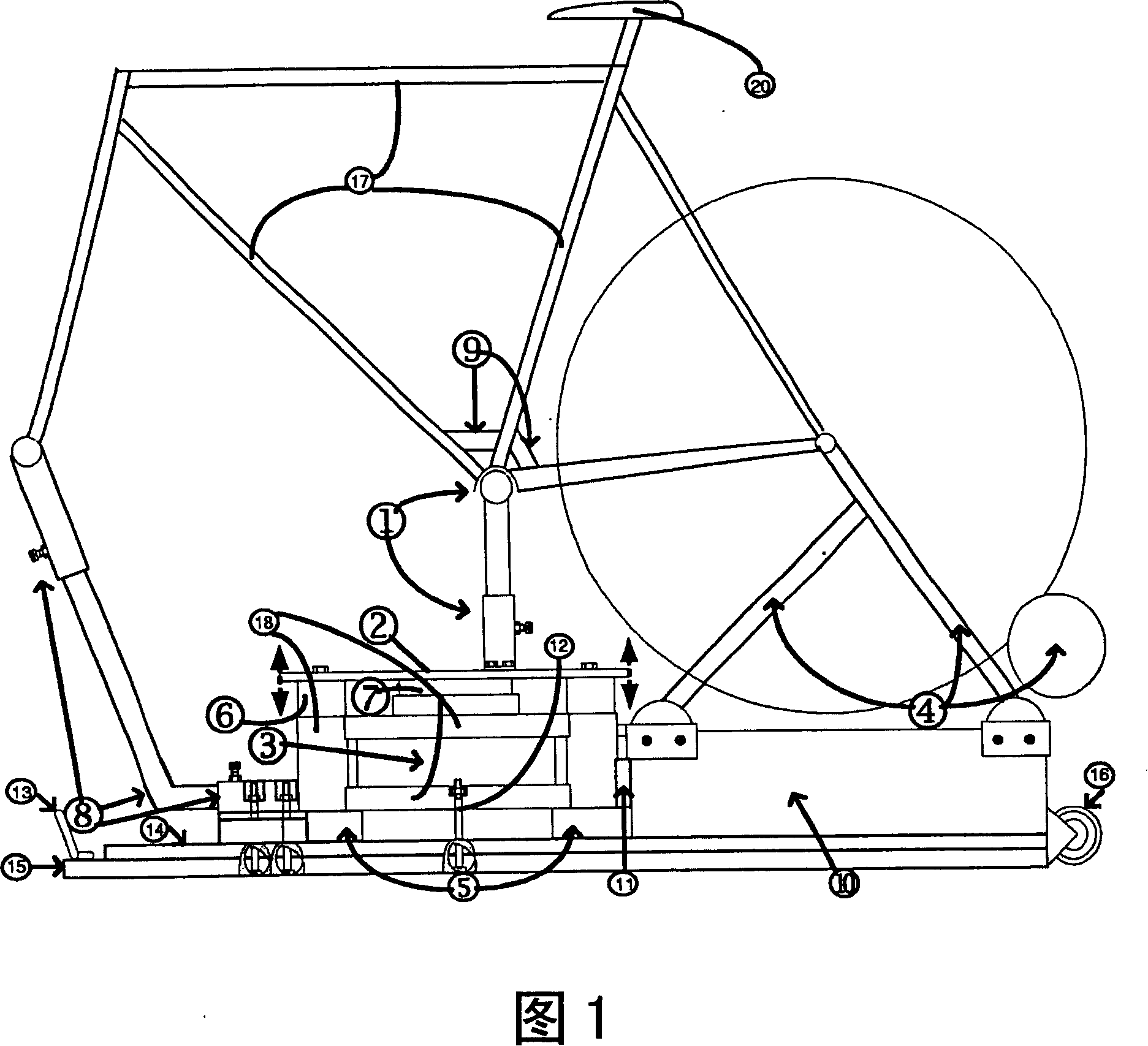
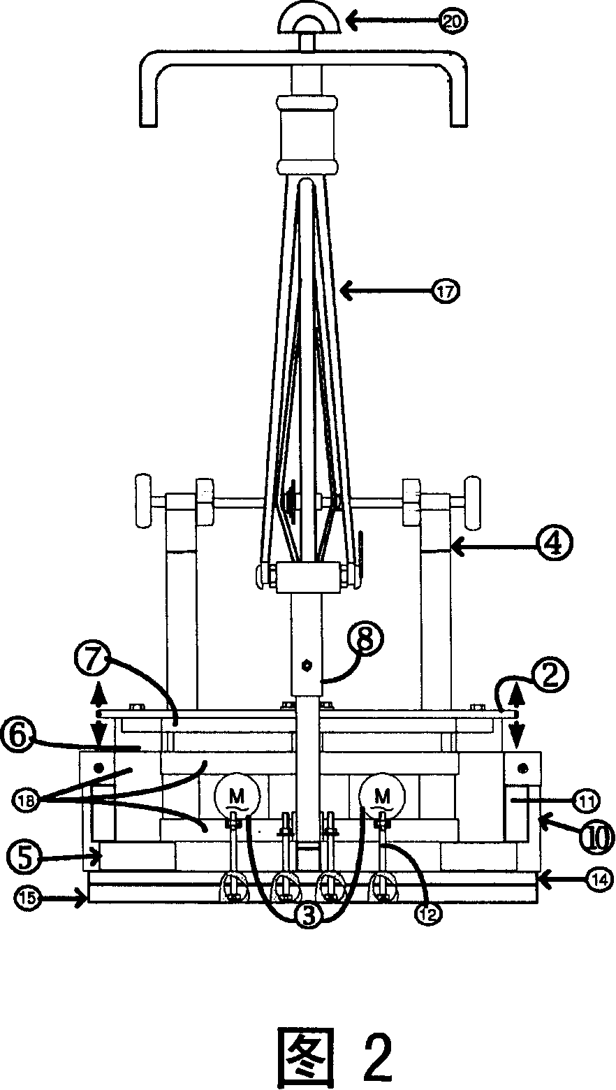
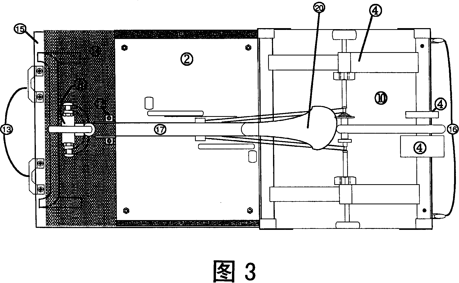
[0053] Figure 1 shows a bicycle vibration dynamometer comprising four structural parts: a vibration table 18 (materials used for this exemplary embodiment: aluminum, solid steel and stainless steel square section tubes), a frame superstructure 17 (Material for this exemplary embodiment: chromium-molybdenum steel alloy), local controller 19 (material for this exemplary embodiment: aluminum / steel sheet) and rear wheel brake resistor 4 (for this exemplary embodiment Way Material: Metal / Plastic).

[0054] Towards the bottom, the vibrating table 18 is provided with floor damping elements 5 for preventing or absorbing vibrations transmitted to the outside. In this exemplary embodiment, these floor damping elements 5 consist of foam boards or rubber-metal dampers, the number and / or hardness of which depends on the required amount of absorption. The vibration element 5 is arranged between two circular washers with metal surfaces, and the floor vibration damping element 5 is mounted t...


PUM


Abstract

The vibration wheel ergometer has a wheel framework upper structure (17) along with a bottom bracket/crank lever (1) which is mechanically decoupled from the framework as well as a vibration unit consisting of vibration plate (2), vibration rack (18) and vibration engines (3). The damping elements (5,6) prevent the transmission of oscillations of vibration unit to the wheel framework upper structure.

Description

technical field [0001] This invention relates to vibrational ergometers and their applications. Background technique [0002] In order to have a positive and effective influence on the individual performance structures of convalescents and elderly patients or competitive athletes, the largest possible doses of external training stimuli must be transferred in a balanced and regulated manner to the various structural levels of the human organism. Among these, elements concerning conditioning (strength, stamina, speed, flexibility) and coordination (neuromotor) should be taken into account within the scope of the application of the training method. [0003] According to the new training alternative, a multitude of vibration training devices leads to optimal physiological performance through the regeneration of pathologically degenerated functional systems of the anatomy or through the improvement of the capacity of the non-impaired functional systems of said anatomy. Although ...

Claims


Application Information

Patent Timeline
Patent Type & Authority Applications(China)
IPC IPC(8): A61H1/02A61H23/02A63B22/06A63B22/08
CPCA61H1/005A61H23/02A61H23/0263A61H2201/1261A63B22/0605A63B22/08A61H2203/0431A61H1/00
Inventor D·考尔兹
Owner D·考尔兹
Why Eureka
Try Eureka