Gear shaping machine with slide board type knife rack

A technology of gear shaping machine and tool holder, which is applied to components with teeth, gear cutting machines, belts/chains/gears, etc. It can solve the problems of small stroke adjustment range, inability to meet the needs of processing strokes in time, and high technical requirements. The effect of enhancing flexibility

Inactive Publication Date: 2008-02-20
南京二机齿轮机床有限公司
View PDF0 Cites 9 Cited by
  • Summary
  • Abstract
  • Description
  • Claims
  • Application Information

AI Technical Summary

Problems solved by technology

In addition, when machining internal teeth, many effective strokes may be wasted because the lower plane of the tool is higher than the upper plane of the workpiece when entering and withdrawing the tool.
[0003] In order to increase the stroke, the traditional method is to increase the height of the column, that is, loosen the connection between the column and the bed and add the height of the set stroke, and then fasten the column and the bed with large bolts. The later gear shaping machine can only process the gears of the modified stroke, and cannot adapt to the original gear processing and new gear processing. It is equivalent to a special-purpose machine tool, and the transformation process is labor-intensive and technically demanding.
[0004] To sum up, none of the existing gear shaping machines can meet the needs of different processing strokes in time, and the stroke adjustment range is very small

Method used


Image

  • Gear shaping machine with slide board type knife rack
  • Gear shaping machine with slide board type knife rack
  • Gear shaping machine with slide board type knife rack

Examples


Embodiment Construction

[0017] The present invention will be further described below in conjunction with the accompanying drawings and embodiments.

[0018] As shown in Figure 1-5.

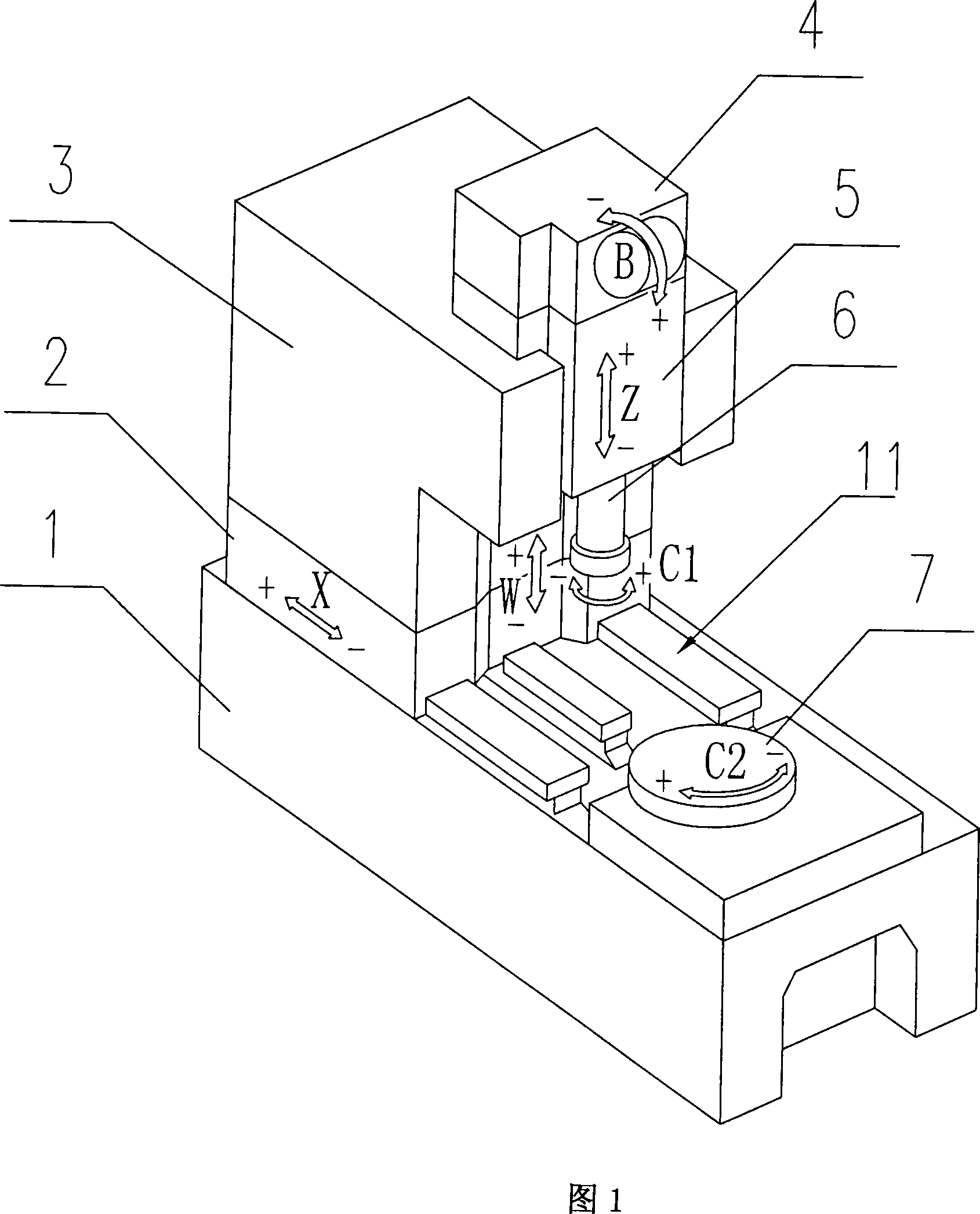
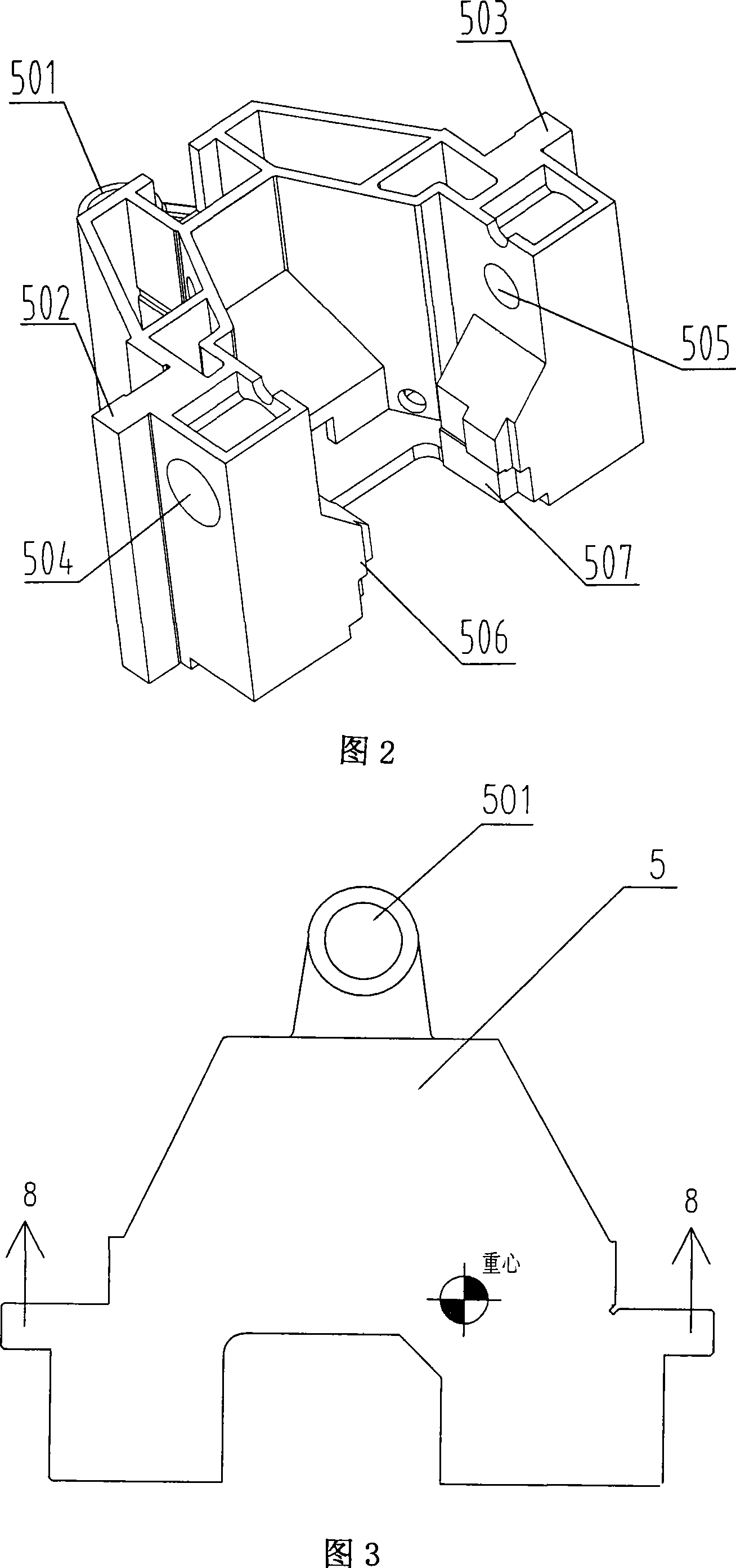
[0019] A gear shaping machine with a slide-type tool holder, including a bed 1, a radial slide 2, a column 3, a transmission box 4, a tool holder slide 5, a tool holder 6, and a workbench 7. As shown in Figure 1, the bed The body 1 is provided with a radial guide rail 11 and a workbench 7, a radial slide plate 2 is installed on the radial guide rail 11, a column 3 is installed on the radial slide plate 2, a tool holder slide plate 5 is installed on the column 3, and a tool holder slide plate 5 The upper part of the tool holder 4 is equipped with a transmission box 4, and the upper end of the tool holder 6 is installed in the tool holder slide plate 5 and connected with the transmission box 4; both sides of the tool holder slide plate 5 are respectively provided with a guide rail 502 that matches the axial guide groove on...


PUM


Abstract

The present invention relates to a gear shaper with a slide-plate-typed knife rest, which comprises a bed body (1) and a standing pole (3). The bed body (1) is provided with a radial guide rail (11) and a working table (7). The radial guide rail (8) is provided with a radial slide plate (2), and the standing pole (3) is positioned on the radial slide plate (2). The present invention is characterized in that: the standing pole (3) is provided with a knife rest slide plate (5), and the knife rest slide plate (5) is provided with a transmission box (4) and a knife rest (6). Two sides of the knife rest slide plate (5) are respectively provided with a guide rail (502, 503), and the back of the knife rest slide plate (5) is provided with a screw sleeve (501) used for driving. The standing pole (3) is provided with a counterweight device (8). The knife rest (6) is positioned in the knife rest slide plate (5) by the supporting holes (504, 505) at two sides of the corresponding knife rest slide plate (5) and the gibs (506,507) at the two lower sides of the installation groove. The present invention realizes the purpose of clamping a plurality of components for one time, which can fit for the processing height of different workpieces, and the heightening cushion block is eliminated for the standing pole, and the flexibility of the machine bed is greatly enhanced. The present invention is especially applied for processing the long shaft in the gear box of the medium and big size cargo vehicle and the deep inner teeth in the engineer mechanism.

Description

technical field [0001] The invention relates to a machine tool, in particular to a gear shaping machine, in particular to a gear shaping machine with a slide tool rest. Background technique [0002] At present, most of the main motions of traditional gear shaping machines adopt one of the two mechanisms, that is, crank slider mechanism or crank rocker mechanism, and the height of the gear shaper tool holder is fixed, so when designing this type of When designing the gear shaping scheme of the machine tool, special attention should be paid to the processing height. In the industrial field, it is very difficult to exchange gear shaper fixtures. In addition, when machining internal teeth, many effective strokes may be wasted in order that the lower plane of the tool is higher than the upper plane of the workpiece when the tool is entering and withdrawing. [0003] In order to increase the stroke, the traditional method is to increase the height of the column, that is, loosen ...

Claims


Application Information

Patent Timeline
Patent Type & Authority Applications(China)
IPC IPC(8): B23F5/12B23F23/12B23F23/00
Inventor 马红民李光华张思全吕福根
Owner 南京二机齿轮机床有限公司
Why Eureka
Try Eureka