Double-worm and worm gear transmission mechanism used for machine tool

A technology of worm gear transmission and double worm, which is applied in the direction of metal processing machinery parts, large fixed members, manufacturing tools, etc., and can solve the problem of inability to position sliding parts

Inactive Publication Date: 2008-02-20
SUZHOU BAOMA NUMERICAL CONTROL EQUIP
View PDF1 Cites 4 Cited by
  • Summary
  • Abstract
  • Description
  • Claims
  • Application Information

AI Technical Summary

Problems solved by technology

In this mechanism, it is very labor-saving and convenient to slide the slider to the appropriate position, but it is impossible to further accurately position the slider

Method used


Image

  • Double-worm and worm gear transmission mechanism used for machine tool
  • Double-worm and worm gear transmission mechanism used for machine tool

Examples


Embodiment

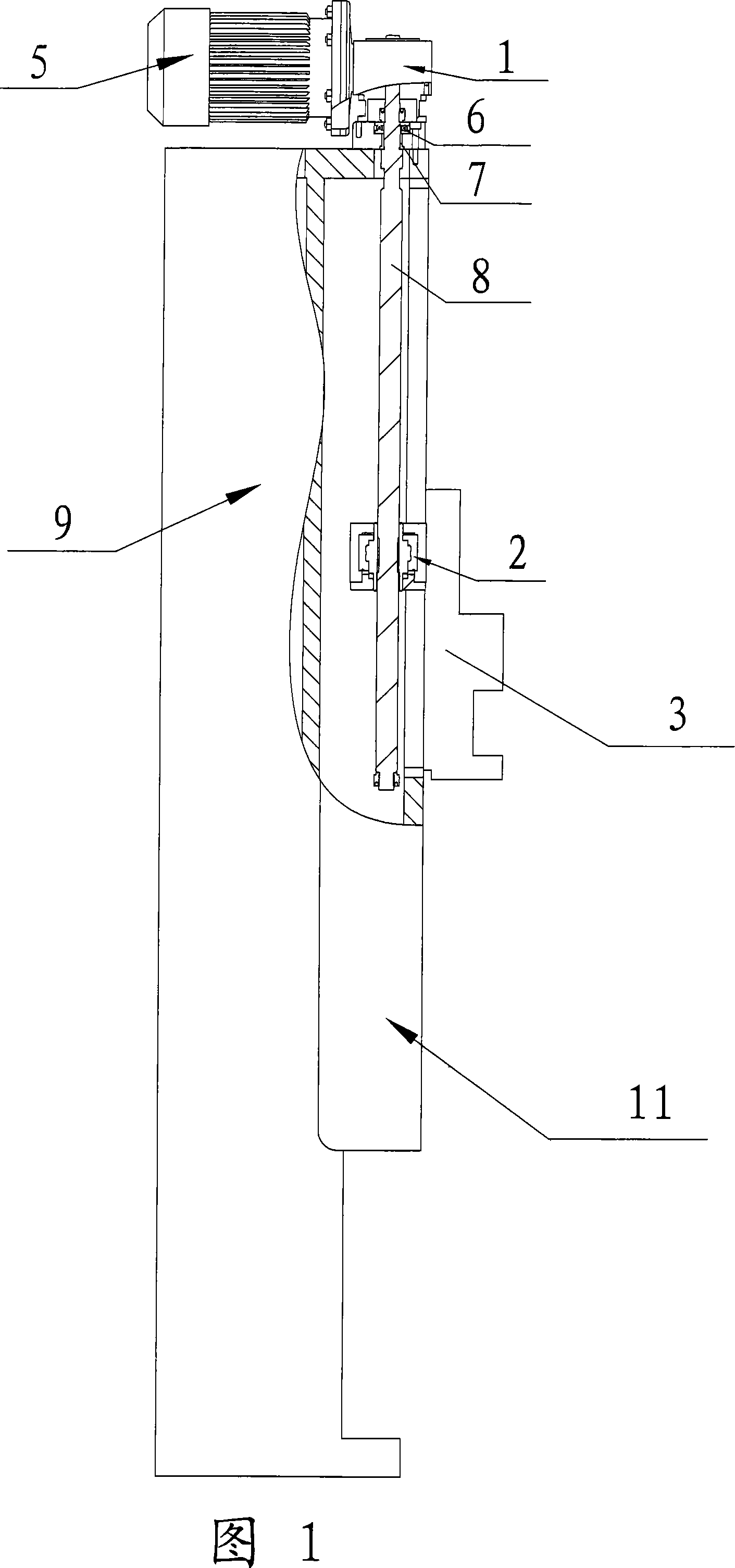
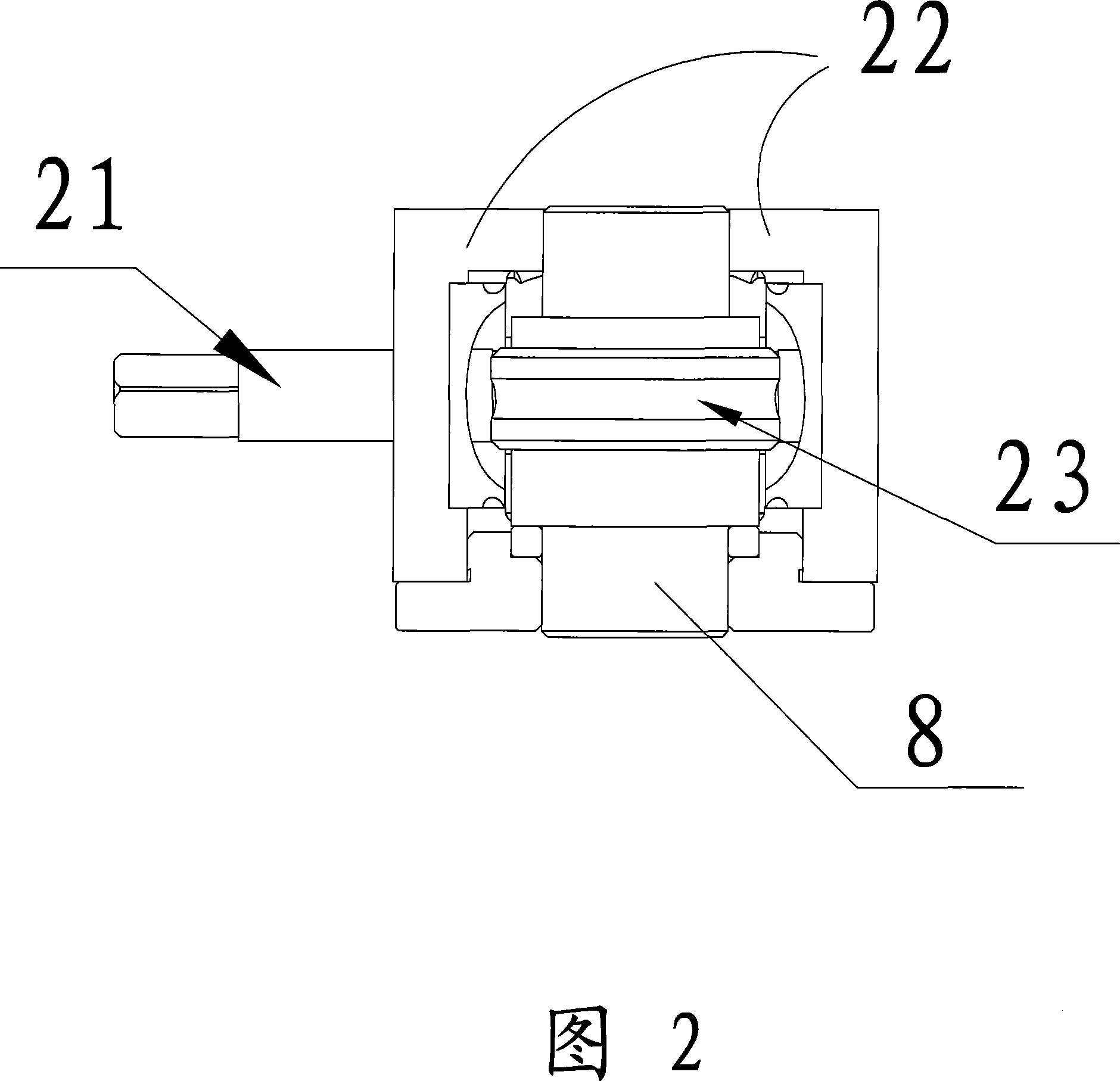
[0016] Referring to Fig. 1, a double worm gear transmission mechanism for a machine tool of the present invention includes a driving device 5, a primary worm gear reducer 1, a bearing 6 arranged on the primary worm gear reducer 1, a screw rod 8, a sliding Part 3, column or carriage 9, limit switch arranged on the column or carriage 9, the drive device 5 is connected with the worm shaft of the first-stage worm gear reducer 1, and the screw rod 8 is connected with the first-stage The worm shaft of the worm gear reducer 1 is vertically arranged and one end thereof is connected with the worm wheel of the first-stage worm gear reducer 1, and the sliding member 3 is slidably arranged with the column or the carriage 9, which also includes a The secondary worm gear reducer 2 on the described screw mandrel 8, as shown in Figure 2, described secondary worm gear reducer (2) comprises worm shaft 21, worm gear box 22, is arranged in worm gear box 22 and Worm wheel 23 with internal thread, ...


PUM


Abstract

The present invention relates to a drive mechanism of twin-worm wheel applied in machine tool, comprising a secondary worm wheel reducer which can be slightly regulated and is arranged on a guide screw; the reducer includes a worm shaft, a worn wheel case, a worm wheel which is arranged in the worm wheel case and has inner screw thread; the inner screw thread engages with the guide screw, the worm shaft is vertical with the guide screw and the worm wheel case is fixedly connected with a sliding element which can be driven to slide along the vertical pole or the dragging board by the worm wheel case. The manual adjustment of the worm shaft on the secondary worm wheel reducer can drive the worm wheel on the secondary worm wheel reducer to move slowly along the guide screw, and the worn wheel case can impel the sliding element to slide along the vertical pole or the dragging board; thus, the position of the sliding element is slightly adjusted, thereby realizing the precise position effect.

Description

technical field [0001] The invention relates to a double worm and worm gear transmission mechanism, in particular to a double worm and worm gear transmission mechanism for machine tools. Background technique [0002] Generally, when the machine tool adjusts the cutting or cutting height or width, it is realized by turning the motor or driving the handwheel. In the actual operation process, on the one hand, it is quite inconvenient to use the hand wheel; on the other hand, if the motor is used to drive, the power is usually large, and the sliding part (usually the tool holder seat for installing the tool) moves quickly and is difficult to control. [0003] In the utility model CN2675316Y (authorized announcement date is February 2, 2005), a worm and worm gear transmission lifting mechanism for wire cutting machine tools was described, which applied the worm and worm gear reducer with large transmission ratio, stable operation and compact structure to the wire cutting machine ...

Claims


Application Information

Patent Timeline
Patent Type & Authority Applications(China)
IPC IPC(8): B23Q1/46B23Q1/28B23H7/26
Inventor 巴逢德
Owner SUZHOU BAOMA NUMERICAL CONTROL EQUIP
Why Eureka
Try Eureka