Hydraulic differential variable-speed case

A continuously variable transmission and hydraulic technology, which is applied in transmission devices, fluid transmission devices, belts/chains/gears, etc., can solve the problems of limited application range, small transmission torque, large structural size, etc., to expand the scope of application and reduce costs Low, well-structured effects

Inactive Publication Date: 2008-02-27
黄兴隆
View PDF0 Cites 5 Cited by
  • Summary
  • Abstract
  • Description
  • Claims
  • Application Information

AI Technical Summary

Problems solved by technology

The manufacturing cost of its steering control system accounts for more than half of the transmission cost
Since the steel belt and the variable diameter steel pulley transmit power through friction, the structure size is large, there are many faults, the transmission torque is small, and the application range is limited.

Method used


Image

  • Hydraulic differential variable-speed case
  • Hydraulic differential variable-speed case

Examples


Embodiment Construction

[0014] The present invention will be further described below in conjunction with accompanying drawing of description:

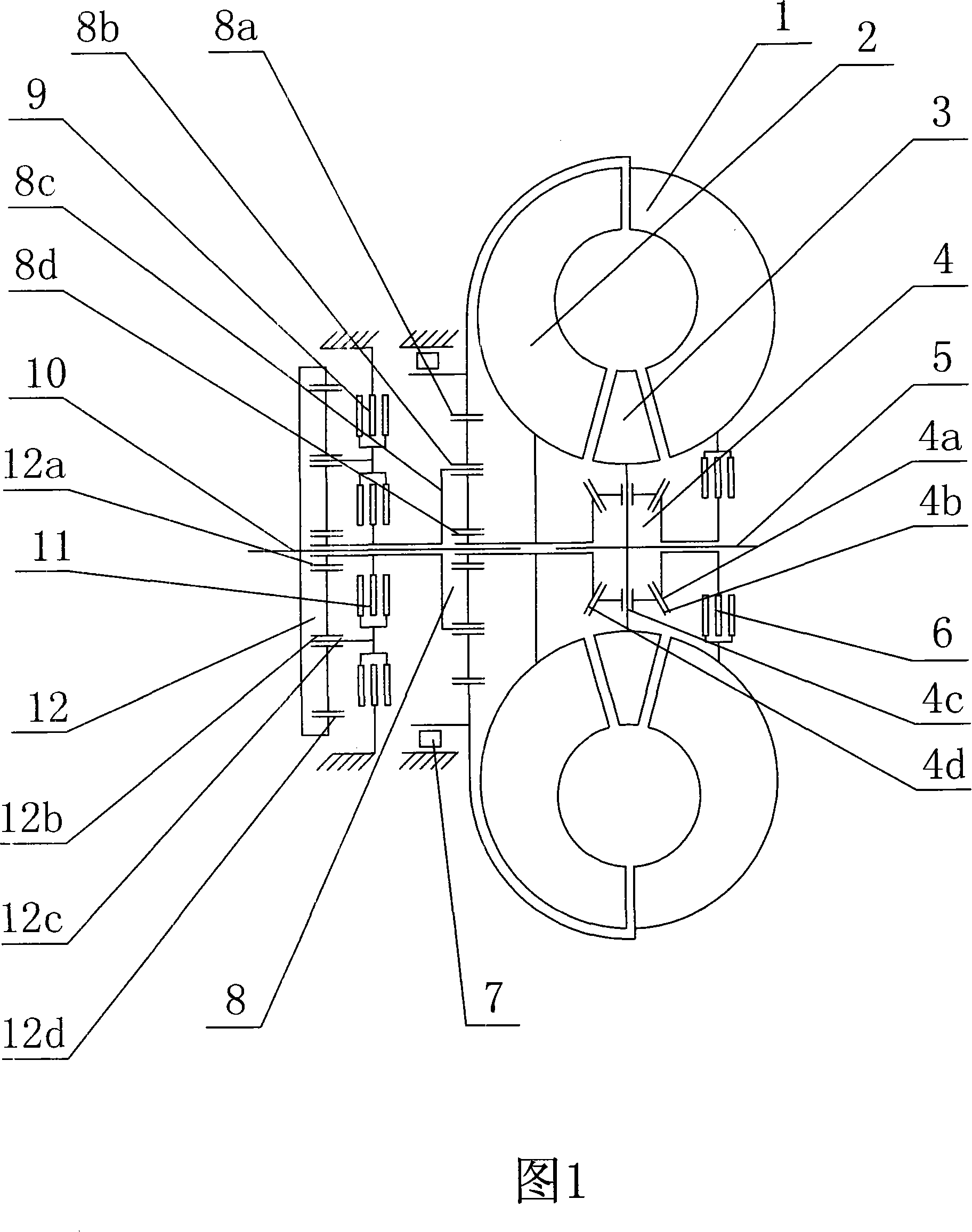
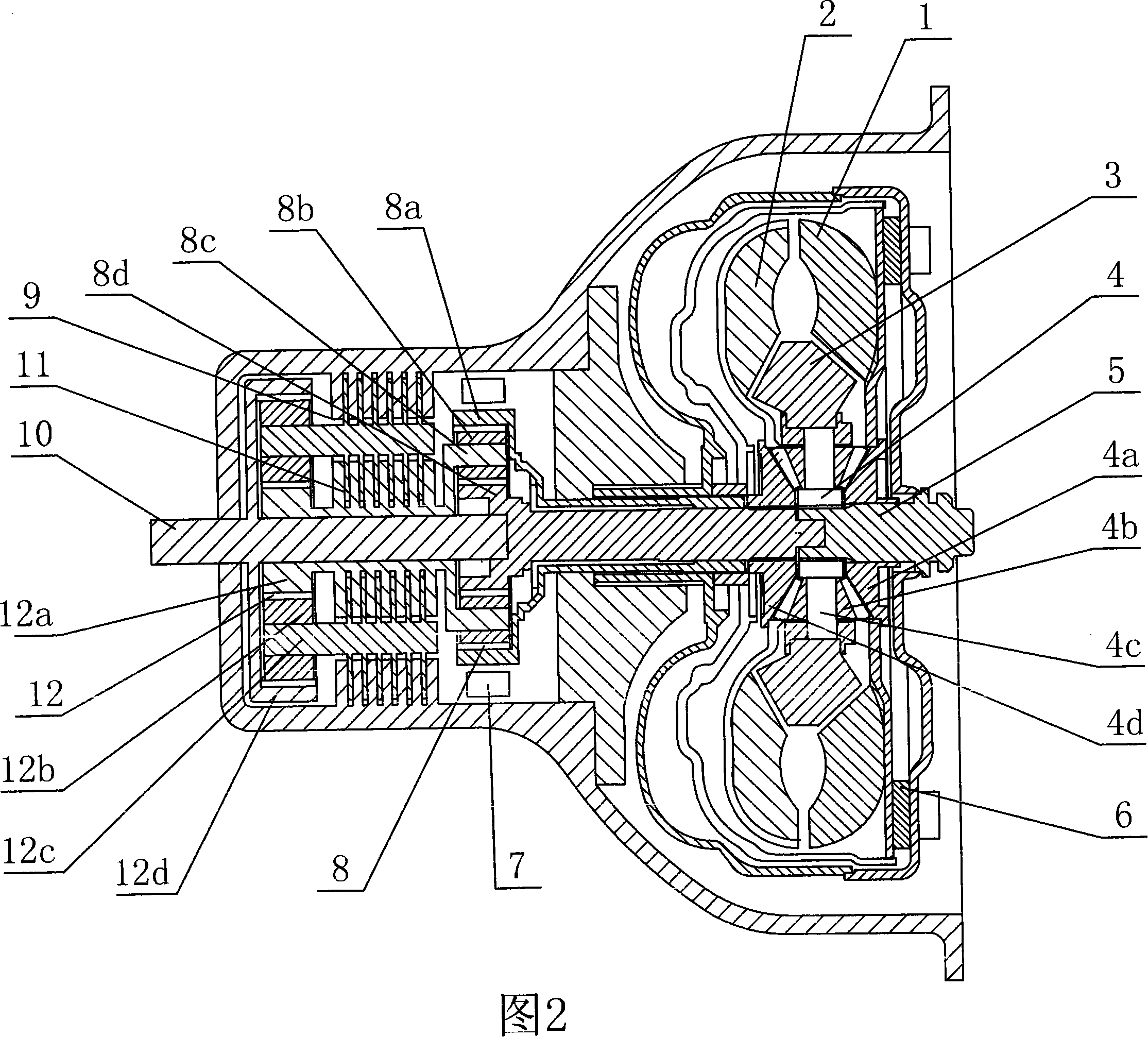
[0015] The hydraulic differential continuously variable transmission consists of a turbine 1, a pump wheel 2, a guide wheel 3, a differential mechanism 4, a speed change planetary row 8, an intermediate clutch 6, and a one-way clutch 7 to form a differential torque converter, and a speed change planetary row 8 It is composed of the variable speed ring gear 8a, the variable speed planetary gear 8b, the variable speed planet carrier 8c, and the variable speed sun gear 8d. The output end of the differential torque converter is connected with the reversing planetary row 12 through the variable speed planetary carrier 8c. The forward gear clutch 11 and the reverse gear clutch 9 are connected and set, the differential mechanism 4 is connected with the input shaft 5, the reversing planet row 12 is connected with the output shaft 10, and the two ends of the variable s...


PUM


Abstract

The hydraulic differential stepless speed variator belongs to the field of stepless speed verifying device technology. The hydraulic differential stepless speed variator consists of one differential torque converter comprising turbine, pump impeller, guide wheel and differential mechanism, speed varying planet mechanism, intermediate clutch and one-way clutch; one speed varying planet mechanism comprising advancing gear clutch, back gear clutch and differential mechanism; and one switching planet mechanism. The differential torque converter, the speed varying planet carrier, the switching planet mechanism and the output shaft are connected successively; and the speed varying sun gear are matched to the input shaft and the output shaft. The hydraulic differential stepless speed variator has novel structure, small size, low cost, direct mechanical driving high driving efficiency and other advantages.

Description

technical field [0001] The invention belongs to the technical field of continuously variable transmissions, and in particular relates to a hydraulic differential continuously variable transmission suitable for connecting engines and driving devices of automobiles, diesel locomotives, tractors, petroleum machinery, mining machinery, ships, and military transportation equipment. Background technique [0002] Continuously variable transmission is the most ideal way of vehicle transmission. The automotive continuously variable transmission (CVT) in the prior art adopts the transmission device of steel belt and variable-diameter steel pulley. The input and output torque status of the engine and transmission system, the monitoring data is converted into electrical signals and transmitted to the microcomputer, and then the computer is compared with the setting program, and instructions are issued after comparison, and various instructions are converted into operating instructions th...

Claims


Application Information

Patent Timeline
Patent Type & Authority Applications(China)
IPC IPC(8): F16H47/08
Inventor 付广振黄兴隆
Owner 黄兴隆
Why Eureka
Try Eureka