Leak indicator comprising a sniffer probe

A technology of leak detection and gas sensor, which is applied in the field of leak detectors and can solve problems such as the adverse effects of the minimum leak rate

Active Publication Date: 2008-02-27
INFICON INC
View PDF1 Cites 7 Cited by
  • Summary
  • Abstract
  • Description
  • Claims
  • Application Information

AI Technical Summary

Problems solved by technology

The minimum leak rate that can be detected is therefore adver

Method used


Image

  • Leak indicator comprising a sniffer probe
  • Leak indicator comprising a sniffer probe

Examples


Embodiment Construction

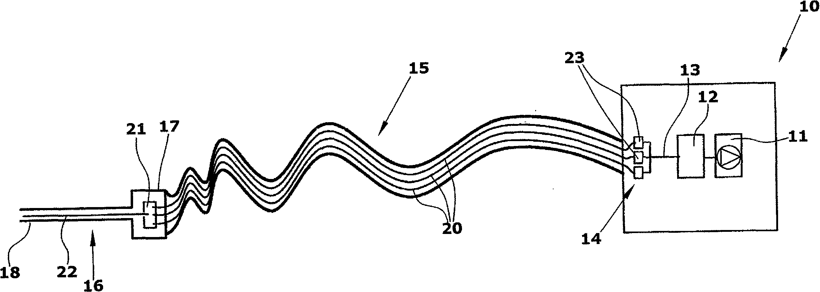
[0020] The leak detector comprises a main device 10 provided with parts that do not have to move during leak testing. The main device 10 is configured as a table-mounted or floor-mounted device. It mainly includes a vacuum pump 11 and a test gas sensor 12 . Mass spectrometers or infrared gas analyzers can be used to test gas sensors. The vacuum pump 11 sucks air through the test gas sensor 12 . The inlet 13 of the test gas detector is connected to a flexible hose line 15 via a valve arrangement 14 . A hose line several meters long extends to the sniffing probe 16 . The sniffer probe 16 is a hand-held device comprising a handle 17 and a sniffer line 18 . The sniffer probe can be designed in the shape of a pistol.

[0021] The hose line 15 comprises a plurality of capillaries 20 which are connected to a line box 21 in the sniffer probe 16 . The line box 21 has a cavity into which an inlet line 22 extending through the sniffing line 18 opens. Inlet line 22 branches in line...


PUM


Abstract

The invention relates to a leak indicator comprising a base unit (10), which contains a vacuum pump (11), a test gas sensor (12) and a hand-held sniffer probe (16). The sniffer probe (16) is connected to the base unit (10) via a flexible hose (15) containing capillary lines (20). According to the invention, the hose is equipped with at least two capillary lines (20), which can be opened using valves (23). This permits different capillary cross-sections to be used. The dead time between the entry of the test gas into the sniffer probe (16) and its detection by the test gas sensor (12) can be modified or selected. This allows the smallest detectable leakage rate to be modified or selected. The leak indicator can be adapted by the user to various requirements, without said user having to change the hose. Different leak indicators of the same equipment family can also be equipped with the same hoses.

Description

technical field [0001] The invention relates to a leak detector with a sniffing probe, which comprises a main device, which includes a vacuum pump and a test gas sensor and is connected to the sniffing probe through a hose line. Background technique [0002] In DE 4445829 A1 (Leybold AG) a countercurrent sniffer leak detector is described which comprises a high vacuum pump stage at the end of the sniffer hose. The leak detector employs a sniffing hose configured as a capillary line with an inner diameter of approximately 0.4 mm and a length of approximately 4 m. The sniffer hose exerts the necessary throttling effect for maintaining the vacuum generated at its outlet end. [0003] DE OS 2441124 describes a leak detection device comprising a sniffer hose which has a relatively large diameter. A throttle valve is provided immediately in front of the test gas sensor, which is a mass spectrometer. Since the throttle valve is arranged immediately in front of the test gas senso...

Claims


Application Information

Patent Timeline
IPC IPC(8): G01M3/20
CPCG01M3/205
Inventor 丹尼尔·韦齐希斯特凡·梅布斯
Owner INFICON INC
Why Eureka
Try Eureka