Sewing machine

A sewing machine and presser foot technology, applied to sewing machine components, sewing machine thread take-up devices, sewing equipment, etc., can solve the problems of poor appearance of sewing products and failure to form the first stitch

Active Publication Date: 2008-03-05
BROTHER KOGYO KK
View PDF1 Cites 11 Cited by
  • Summary
  • Abstract
  • Description
  • Claims
  • Application Information

AI Technical Summary

Problems solved by technology

When the end of the upper thread comes off, there is a problem that the first stitch cannot be formed
In addition, there is also a problem that the bobbin thread after the second stitch is wound many times at the end of the

Method used


Image

  • Sewing machine
  • Sewing machine
  • Sewing machine

Examples


Embodiment Construction

[0034] The present invention will be described in detail below with reference to the drawings showing preferred embodiments.

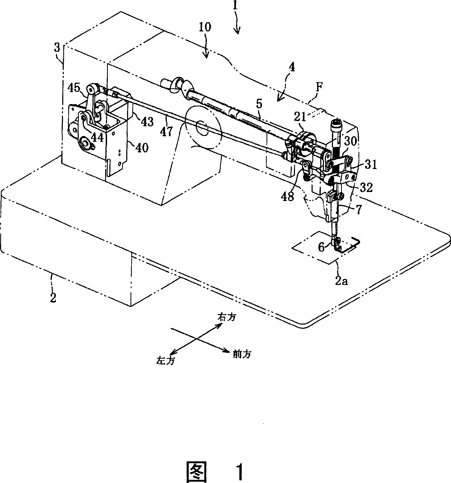
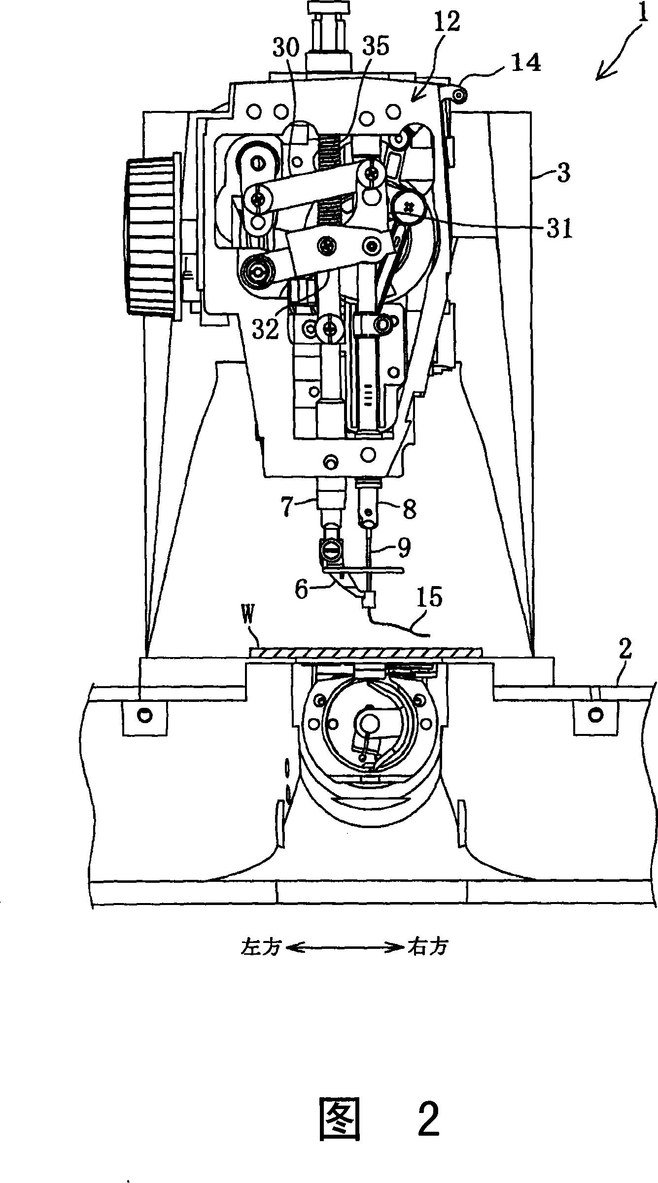
[0035] As shown in FIG. 1 , a sewing machine 1 includes: a bottom plate 2 , a column 3 , and a casing 4 . The upright column 3 is provided in a form standing upward from the rear end portion of the base plate 2 (the upper left in FIG. 1 is the rear). The cabinet 4 is provided in a form extending forward from the upper end of the column 3 . Inside the casing 4, the main shaft 5, which is driven to rotate by a sewing machine motor 63 (see FIG. 12), is arranged along the front-rear direction. As shown in FIGS. 1 and 2 , a needle bar 8 and a pressing bar 7 are provided at the front end of the casing 4 . A detachable sewing needle 9 is installed at the lower end of the needle bar 8 protruding below the casing 4 . A presser foot 6 is fixed to a lower end of a press bar 7 protruding below the cabinet 4 .

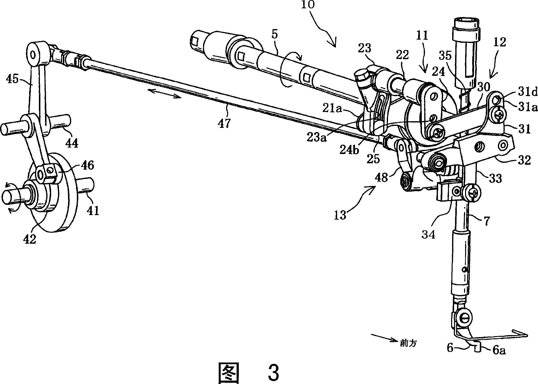
[0036] The presser foot vertical drive device 10 ...


PUM


Abstract

The invention provides a sewing machine, comprising a pressure foot control part for controlling an actuator of an up-down moving changing mechanism, thereby the moving range of the pressure foot is changed downward during sewing in defined needls from sewing beginning, the up-down moving changing mechanism comprises a pressure foot up-down moving position changing mechanism of the up-down moving pressure foot range changed by the actuator upward-downward and moved with the sewing motion synchronistically upward-downward. By utilizing an up-down moving pressure foot moved in the inferior moving range to press the upper thread end part extended from the needle hole of the needle on the processing cloth, thereby friction impedance is applied. The sewing machine can prevent the upper thread end part running out from the lower side of the processing cloth, utilizes a simple structure without an upper thread crowding mechanism to form thread track from the first needle.

Description

technical field [0001] The present invention relates to a sewing machine having a presser foot vertically moving up and down synchronously with sewing needles. Background technique [0002] Sewing machines having a cylindrical presser foot that moves up and down synchronously with the up and down movement of sewing needles are widespread. [0003] For example, a sewing machine disclosed in Japanese Patent Application Laid-Open No. 2006-122230 (2006) includes a vertical drive device for vertically moving a cylindrical presser foot. The vertical driving device operates in a form that the cylindrical presser moves up and down synchronously with the vertical movement of the sewing needle. The lowered presser presses the upper surface of the processing cloth so as to surround the outer periphery of the sewing needle, and prevents the processing cloth from lifting. When feeding the cloth, the presser foot rises so as not to interfere with the feeding of the processed cloth. [...

Claims


Application Information

Patent Timeline
IPC IPC(8): D05B19/12D05B29/06D05B49/00D05B27/00
CPCD05B19/12D05B29/02D05B49/02D05B69/30D05D2305/32
Inventor 高际丰
Owner BROTHER KOGYO KK
Why Eureka
Try Eureka