

Conveyor having cooling down function and cooling down slag method
A conveyor and conveyor conveying technology, applied in the field of conveyor and its cooling ash, can solve the problems of consuming process time and financial resources, increase the overall process complexity, etc., to improve process safety, improve work efficiency, The effect of reducing the heat load
- Summary
- Abstract
- Description
- Claims
- Application Information
AI Technical Summary
Problems solved by technology
Method used
Image

Examples
Embodiment 1
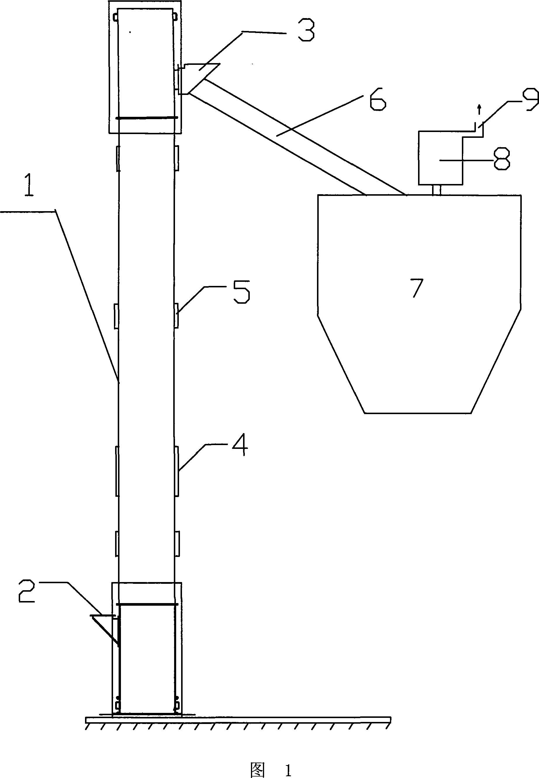
[0031] As shown in Figure 1, Figure 1 is a front view of a conveyor set vertically to the ground with an induced draft fan and an air outlet set on the top of the slag storage bin. It can be seen from the figure that the conveyor installed perpendicular to the ground has a sealed casing 1, and a feed inlet 2 is set at the bottom of the sealed casing 1 and at a certain height from the ground, such as 1.5m; at a position close to the top of the sealed casing A material outlet 3 is provided, and the material inlet 2 and the material outlet 3 are located on different sides of the sealed casing 1 . Of course, in other embodiments, the feed port 2 and the discharge port 3 can also be arranged at other different positions, for example, on the same side of the shell, which will not be repeated here; an inspection door 4 is respectively set on both sides of the sealed shell 1 , In other embodiments, a larger number of inspection doors 4 can also be set.
[0032] In addition, a conveyi...
Embodiment 2
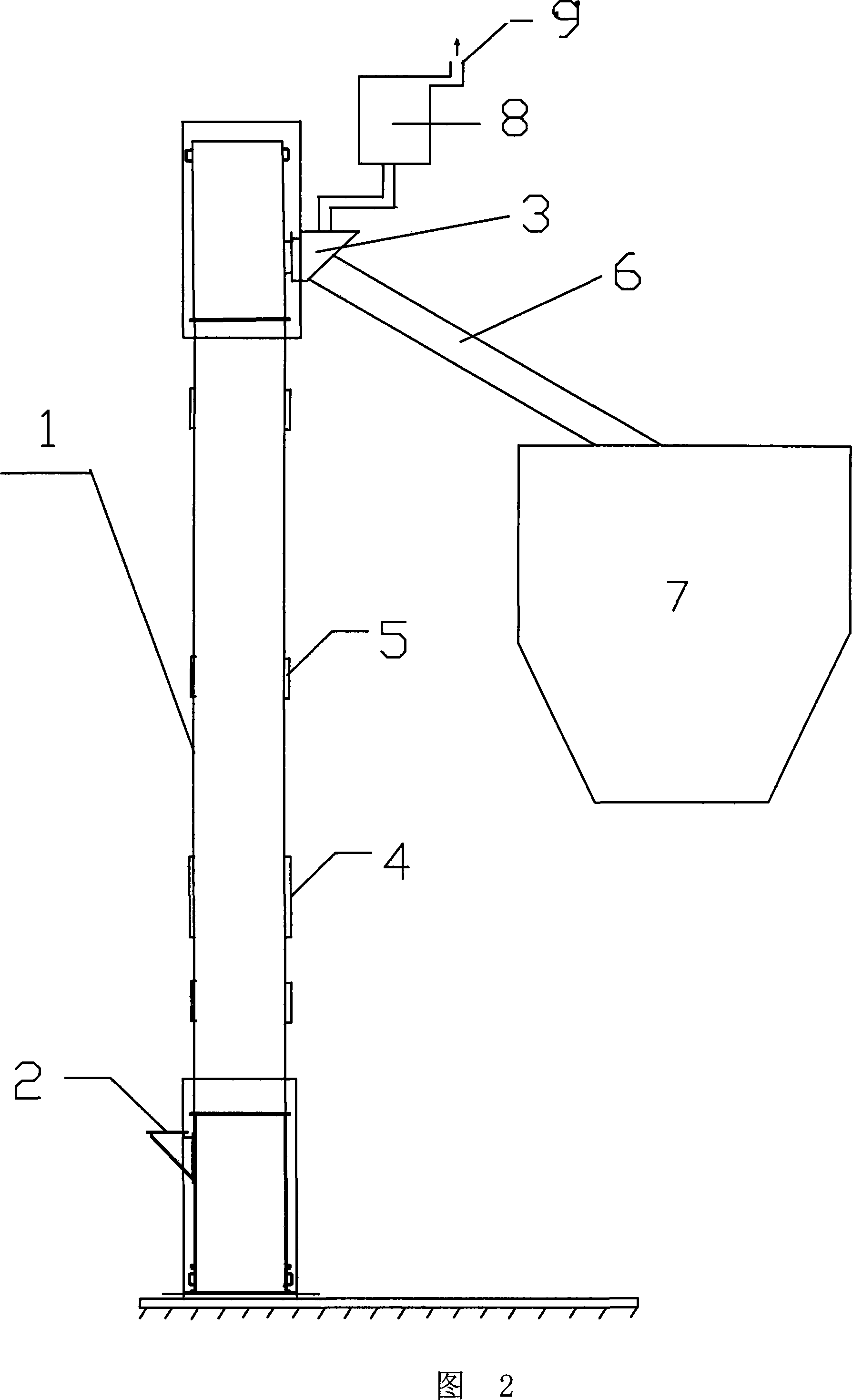
[0040] As shown in FIG. 2 , it is a front view of a conveyor in another embodiment of the present invention. The conveyor is still vertical to the ground, and the induced draft fan and the air outlet are arranged at the discharge port. Compared with FIG. 1 , the difference of this embodiment is that the positions of the induced draft fan 8 and the air outlet 9 are different. In FIG. 2 , the induced draft fan 8 and the air outlet 9 are arranged on the top of the discharge port 3 . Compared to the design shown in Figure 1, which only facilitates air circulation within the conveyor itself, the design in Figure 1 facilitates both the conveyor and the slag connected by the conveying piping The circulation of the wind inside the warehouse as a whole. At the same time, it should be noted that, in order to avoid the ash phenomenon at the discharge port that may be caused by the design shown in Figure 2, the pipeline connecting the discharge port 3 and the induced draft fan 8 is speci...
Embodiment 3
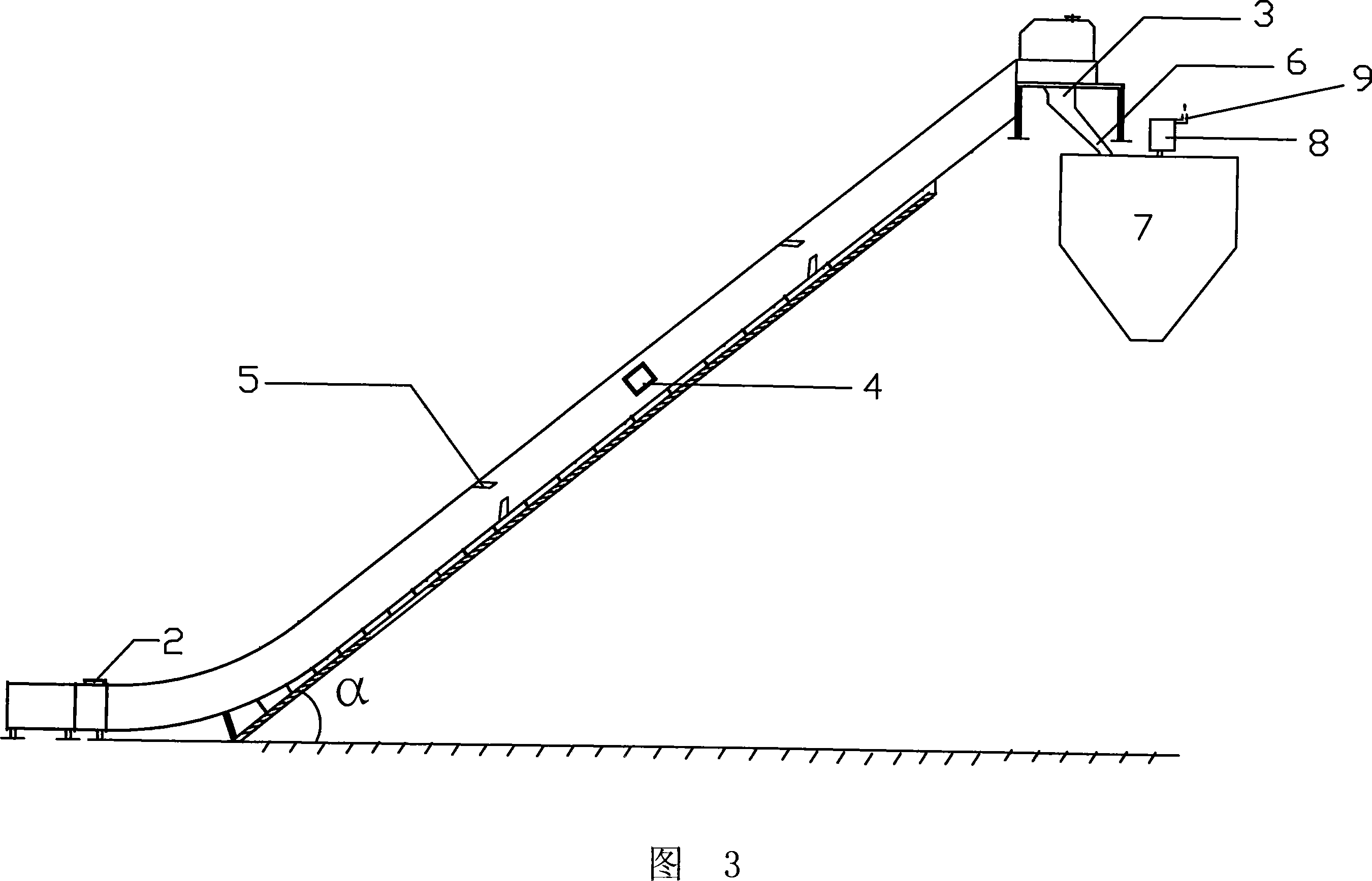
[0043] The conveyor in this embodiment is arranged inclined to the ground, and there is an angle α between the sealed casing 1 and the ground. All the other are with embodiment 1.
[0044] Please see Fig. 3 , which is a side view of a conveyor whose inclination angle α between the sealed casing 1 and the ground is 15-60°. The angle α is preferably 40°. It can be seen from the figure that except for the setting angle, its structure is basically the same as that of the conveyor shown in Figure 1; there are 2 inlets, 3 outlets, 4 maintenance doors, 5 air inlets, and 6 conveying pipes. , storage bin 7, induced draft fan 8 and air outlet 9. In addition, in order to maintain the stability of the inclined airtight enclosure, a stabilizing bracket is provided at the lower part of the airtight enclosure.
[0045] The induced draft fan 8 and the air outlet 9 of this inclined conveyor can also be arranged on the top of the discharge outlet 3 through a zigzag sealed duct as in the embo...
PUM
 Abstract
Description
Claims
Application Information