Vapour compressing refrigeration system including injector

A vapor compression and refrigeration system technology, applied in irreversible cycle compressors, refrigerators, compressors, etc., can solve the problems of cost increase and complex structure, and achieve the effect of simple and practical defrosting operation

Inactive Publication Date: 2008-03-05
XI AN JIAOTONG UNIV
View PDF3 Cites 24 Cited by
  • Summary
  • Abstract
  • Description
  • Claims
  • Application Information

AI Technical Summary

Problems solved by technology

There are also some ejector design concepts, such as the Chinese patent (ZL 03136281.8) applied by Denso Co., Ltd., because considering that the nozzle and the diffuser section need to adapt to maintain a relatively high performance in a relatively wide...

Method used


Image

  • Vapour compressing refrigeration system including injector
  • Vapour compressing refrigeration system including injector

Examples


Embodiment Construction

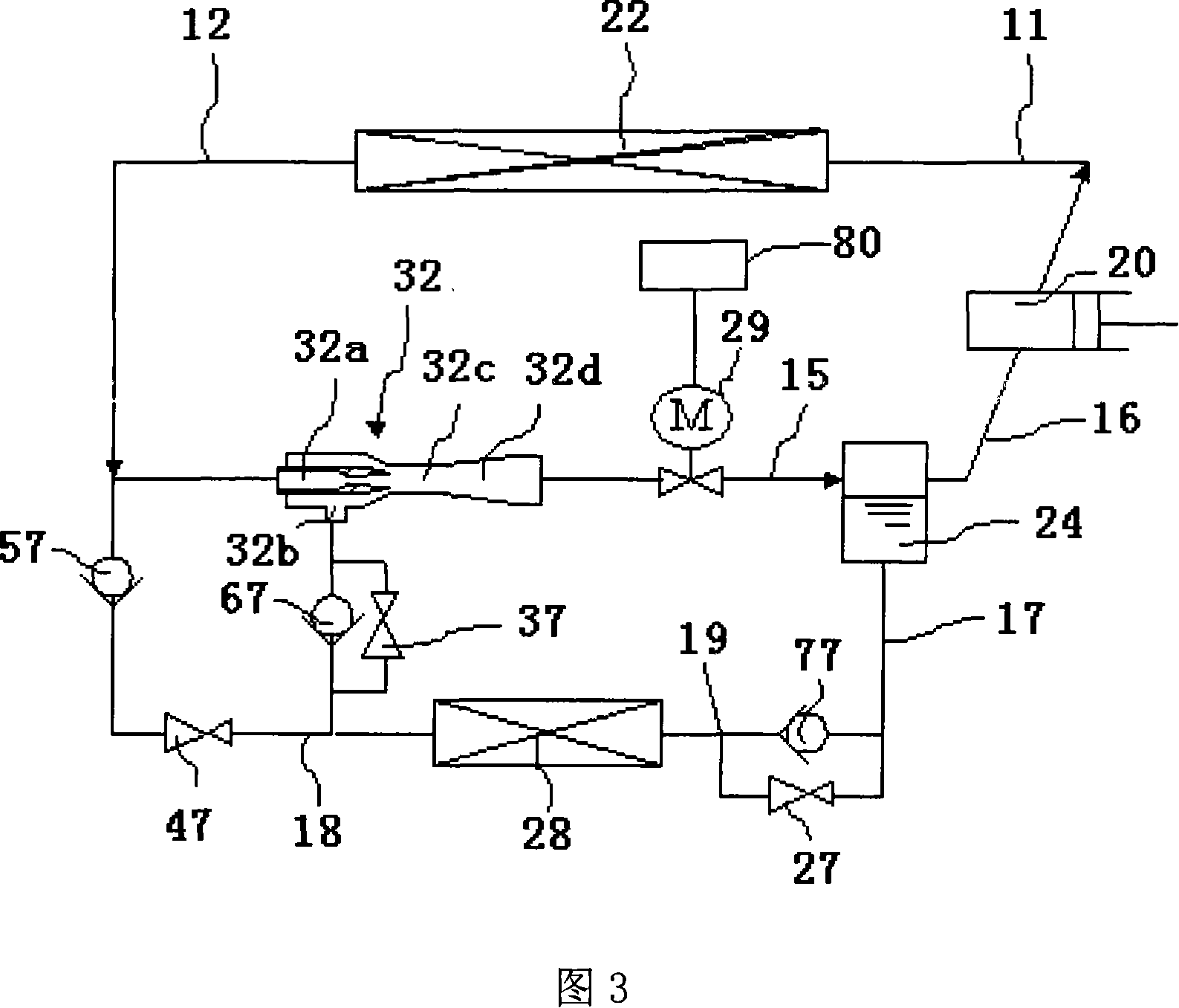
[0018] Referring to Fig. 3, the vapor compression refrigeration system comprising an ejector of the present invention includes a compressor 20, the outlet end of the compressor 20 is connected to a radiator 22, the inlet end of the compressor 20 is connected to a gas-liquid separator 24, and the gas-liquid separator 24 is connected to the diffuser section 32d of the ejector 32 through a valve 29, and the valve 29 is connected to the controller 80;

[0019] The radiator 22 communicates with the nozzle 32a of the ejector 32 through the pipeline 12, and connects the first throttling element 47 through the pipeline 17, the first throttling element 47 communicates with the evaporator 28 through the pipeline 18, and the pipeline 18 passes through The second throttling element 37 and the second one-way valve 67 connected in parallel with the second throttling element 37 are connected to the ejector suction chamber 32b, and the evaporator 28 passes through the pipeline 19, the third th...


PUM


Abstract

The invention discloses a vapor compression refrigerating system with ejector. It includes compressor, air-liquid separator, radiator, ejector and evaporator. The compressor outlet is connected with the radiator, the compressor inlet is connected with the air-liquid separator; the air-liquid separator is connected with diffusing section of the ejector via a valve; the valve is connected with controller; the radiator is connected with ejector nozzle via pipeline and is connected with first throttling element via the pipeline; the first throttling element is connected with the evaporator through pipeline and is connected with secondary throttling element and secondary one-way valve paralleled with the secondary throttling element to ejector suction chamber by pipeline; the evaporator is connected with the liquid end of air-liquid separator; the air end of air-liquid separator is connected with the compressor via pipeline.

Description

technical field [0001] The invention relates to a vapor compression refrigeration system, in particular to a vapor compression refrigeration system comprising an ejector, the system adopts the ejector as a vapor compression cycle of the main throttling element, and can be used in vapor compression refrigeration and heat pump devices . Background technique [0002] In the vapor compression cycle, after the refrigerant is compressed by the compressor, it is discharged into the condenser by the compressor, releases heat to a high-temperature heat source and condenses, and is throttled when it passes through a throttling element (such as a capillary tube, expansion valve). Both the pressure and temperature are reduced, and then enter the evaporator, absorb heat from a low-temperature heat source and evaporate, and finally re-enter the compressor to be compressed, completing a complete cycle. [0003] In 1966, C.A.Cemper of the United States applied for the patent No. US 3277660...

Claims


Application Information

Patent Timeline
IPC IPC(8): F25B9/08F25B1/00
Inventor 邓建强张早校强科韦帮远
Owner XI AN JIAOTONG UNIV
Why Eureka
Try Eureka