
Dynamic speed testing method

A speed measurement and dynamic technology, applied in optical devices, measurement devices, linear/angular velocity measurement, etc., can solve the problems of police speeding violations and drivers speeding violations, etc., to ensure traffic safety and safety. The effect of smooth and preventing speeding violations

Inactive Publication Date: 2008-03-05
SOUTHERN TAIWAN UNIVERSITY OF TECHNOLOGY
View PDF0 Cites 20 Cited by
  • Summary
  • Abstract
  • Description
  • Claims
  • Application Information

AI Technical Summary

Problems solved by technology

[0004] Other existing speed detectors all use the same GPS positioning system to evade police speeding checks, thus causing drivers to be more reckless in speeding violations, making it even more difficult for the police to crack down on speeding violations

Method used


Image

  • Dynamic speed testing method
  • Dynamic speed testing method

Examples


Embodiment Construction

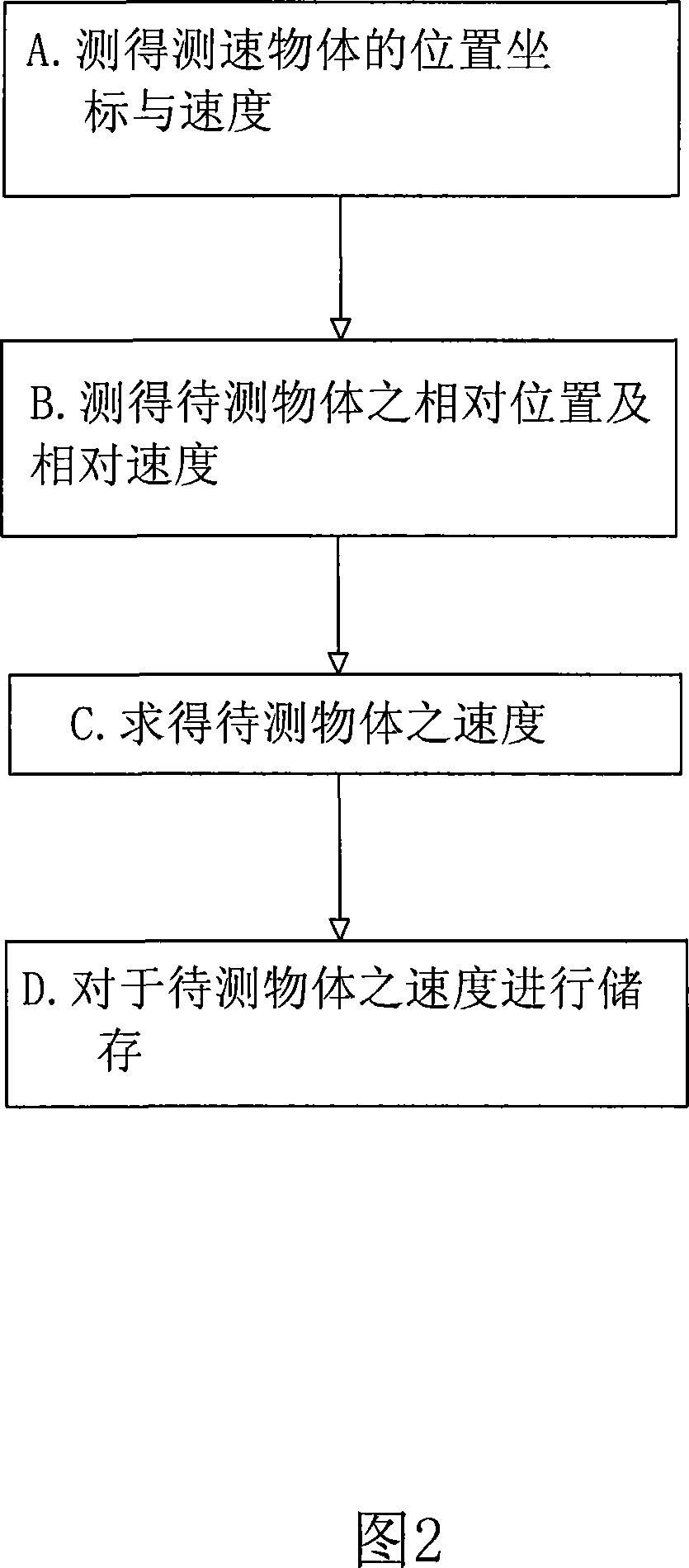
[0019] At first, referring to shown in Fig. 1, the present invention mainly comprises the following steps:

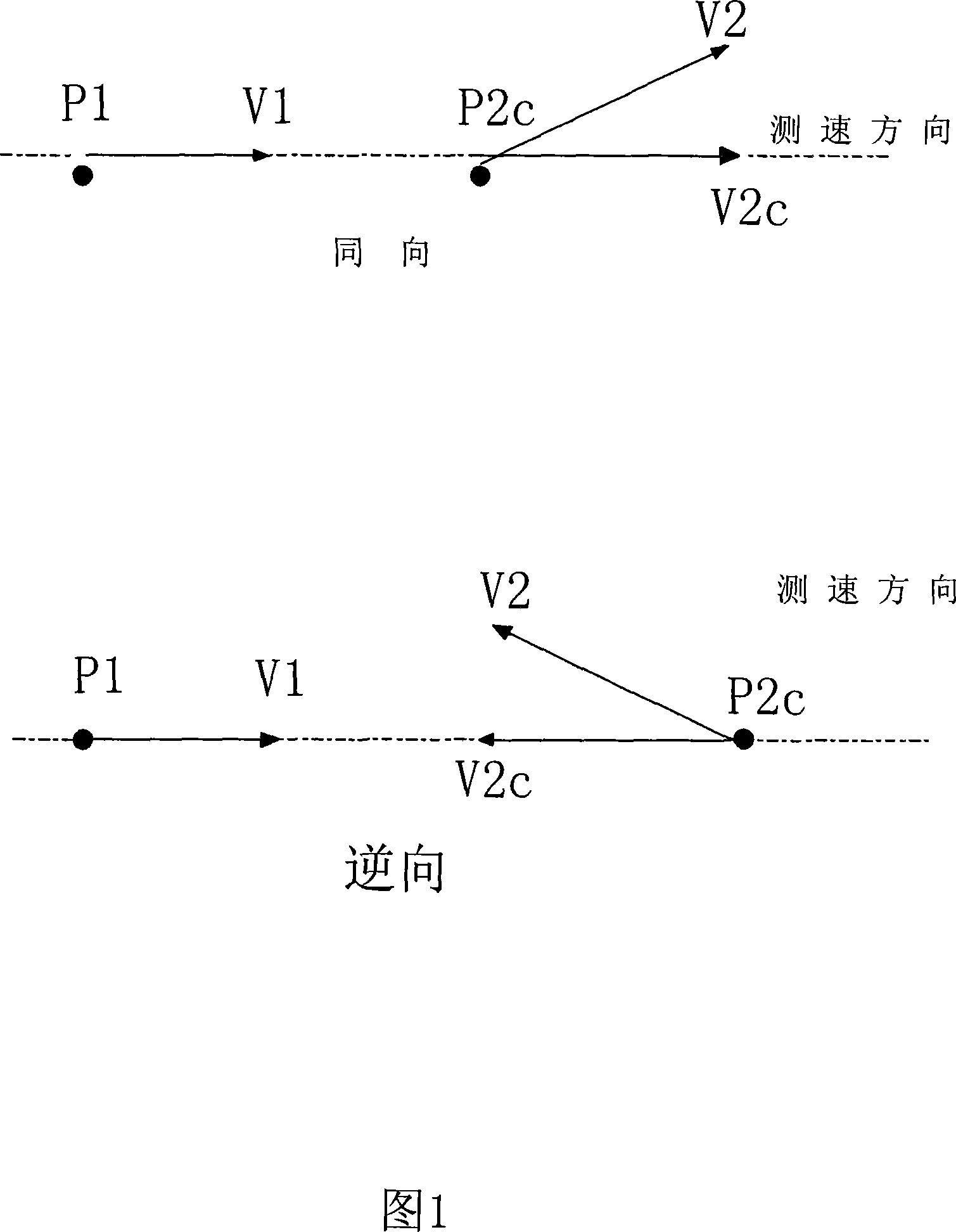
[0020] A. Measure the position coordinates and speed of the speed measuring object; it uses the Global Position System (GPS) to transmit signals to measure the position coordinates and speed of the speed measuring object. The speed measuring object system can be a moving police car .

[0021] B. Measure the relative position and relative speed of the object to be measured; it uses the speed measuring unit on the speed measuring object to measure the relative position and speed of the object to be measured. It is a device such as speed measuring radar / laser, which can measure the relative position and relative speed between the speed measuring object and the object to be measured.

[0022] C. Obtain the speed of the object to be measured; use the processing unit to calculate the position coordinates and speed of the speed measurement object, as well as the relative posi...


PUM


Abstract

The method comprises: a) testing the location coordinate and speed of the object under test; b) testing the relative location and relative speed of the object under test; c) figuring out the speed of the object under test; d) saving the speed of the object under test. The invention can be used in police car to test the tested object such as over-speed car.

Description

Technical field: [0001] The present invention relates to a dynamic speed measuring method, which mainly lies in that it can cooperate with the global satellite positioning system (GPS) to transmit signals to measure the position coordinates and speed of a moving police car, and then use the speed measuring unit on the police car to measure The relative position and relative speed of the speeding vehicle are used to obtain the speed of the violating vehicle, which is used as the basis for the prohibition of speeding violations. Background technique: [0002] At present, in order to maintain driving safety and improve traffic chaos, traffic management units will set different speed limits for different road conditions, and set up speed measuring equipment to provide evidence to law-breaking people by taking photos; At present, the common types of speed measuring radars can be mainly divided into American regulations, European regulations and fixed camera systems. Generally, ra...

Claims


Application Information

Patent Timeline
IPC IPC(8): G01P3/00G01P3/36G01S13/60G01S1/02G01S1/08G08G1/052G01S19/52
Inventor 许毅然
Owner SOUTHERN TAIWAN UNIVERSITY OF TECHNOLOGY
Learn More