Compact multi-level output hybrid gas generator

A technology of gas generators and gas generating parts, which is applied in transportation and packaging, vehicle parts, pedestrian/passenger safety arrangements, etc., and can solve problems such as complex devices

Inactive Publication Date: 2008-03-05
ARC AUTOMOTIVE
View PDF2 Cites 5 Cited by
  • Summary
  • Abstract
  • Description
  • Claims
  • Application Information

AI Technical Summary

Problems solved by technology

However, this device is more complex than that described in US Patent No. 3,773,353

Method used


Image

  • Compact multi-level output hybrid gas generator
  • Compact multi-level output hybrid gas generator
  • Compact multi-level output hybrid gas generator

Examples


Embodiment Construction

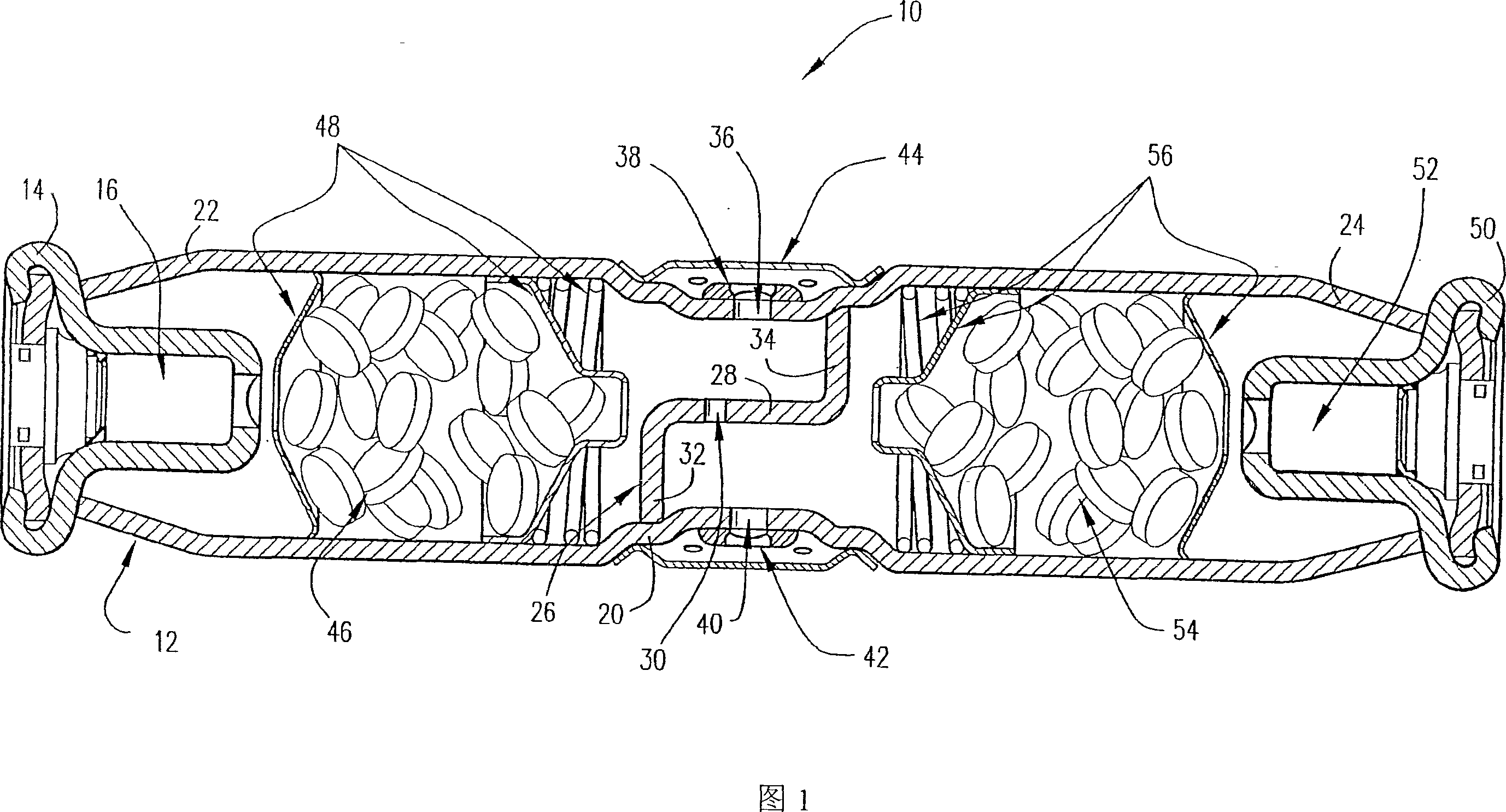
[0032] Figure 1 illustrates a multi-stage output inflator or gas generator 10 according to one embodiment of the present invention. The inflator 10 includes an elongated pressure vessel 12 made of any suitable material, such as steel, aluminum or other material. An igniter body 14 of any suitable material, such as steel, aluminum or other material, is secured to the pressure by any suitable means, such as crimping or friction welding. One end of the tube 12. The ignition body 14 supports a primary ignition device 16 of any suitable construction. The main ignition device 16 can be an initiator or a microgas generator.

[0033]The pressure tube 12 is preferably formed with an indented portion 20 of any suitable configuration near its center. The concave portion 20 is used to form a primary gas generating portion 22 between the primary ignition device 16 of the pressure tube 12 and the concave portion 20 , and the concave portion 20 is opposite to the pressure tube 12 A secon...


PUM


Abstract

A multi-level gas inflator for an air bag or other safety device, comprising an elongated pressure vessel having a primary gas generant portion with a first open end and a secondary gas generant portion with a second open end. The primary gas generant portion has a primary ignition device and primary gas generating energetics disposed therein. The primary ignition device is mounted on and closes the pressure vessel at the first open end thereof. The secondary gas generant portion has a secondary ignition device and secondary gas generating energetics disposed therein. The secondary ignition device is mounted on and closes the pressure vessel at the second open end thereof. A suitable gas under a predetermined pressure is present in the primary and secondary gas generant portions. One or more dividers or divider walls are disposed within the midportion of the pressure vessel to separate the primary and secondary gas generant portions. The pressure vessel has a primary exit orifice in the midportion thereof that is in communication with the primary gas generant portion, and a secondary exit orifice in the midportion thereof that is in communication with the secondary gas generant portion. A primary rupture disk is disposed over the primary exit orifice, and a secondary rupture disk is disposed over the secondary exit orifice. A diffuser is mounted on and surrounds the pressure vessel midportion and the primary and secondary exit orifices. The diffuser is in communication with the air bag for the inflation thereof. The inflator can be easily converted to a single level output inflator by omitting the secondary ignition device and the secondary gas generating energetics.

Description

technical field [0001] The present invention relates to an inflator or gas generator for airbags or other safety equipment, in particular, to a small hybrid gas generator with multi-stage output, which can be selected at different speeds and levels Airbags or other types of safety devices can be deployed or deployed at different output levels based on different sensor inputs. Background technique [0002] Recently, there has been a need to control the speed and amount of inflation or to control the movement of safety devices such as air bag restraint systems according to variable factors such as number of passengers, location, use of seat belts and the speed of the vehicle at the moment of collision. [0003] For optimum occupant protection, air bag inflators need to have different output levels. For example, when a high-speed collision occurs with a large person who is not wearing a seat belt, the airbag needs to inflate at full speed to provide the best protection. When...

Claims


Application Information

Patent Timeline
Patent Type & Authority Applications(China)
IPC IPC(8): B60R21/26B60R21/272
CPCB60R2021/2633B60R21/272B60R21/263B60R21/2338B60Y2304/07B60R2021/2612
Inventor 大卫·A·比尔布雷斯科特·约瑟夫·科尔伯恩理查德·C·赫斯本德罗伯特·W·罗维托塞缪尔·摩根·汉考克
Owner ARC AUTOMOTIVE
Why Eureka
Try Eureka