Pot utensils ' movement device and cooking device adopting said pot utensils ' movement
A technology of movement device and cooking equipment, applied in the field of pot movement device and cooking equipment, can solve the problems of limited turning function and the like
- Summary
- Abstract
- Description
- Claims
- Application Information
AI Technical Summary
Problems solved by technology
Method used
Image
Examples
Embodiment 1
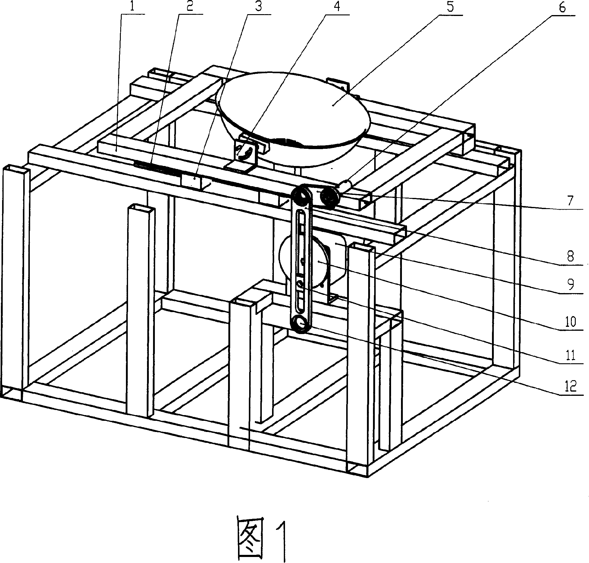
[0056]See Figure 1. The pot 5 is installed on the translation frame 1 through the angle adjuster 4, and the angle adjuster 4 can adjust and set the angle between the pot and its moving direction. The motor 9 (the first driving device) drives the turntable crank 10 to rotate, so that the slider 11 slides in the long hole of the rocker 8, and the rocker 8 is moved to swing clockwise / counterclockwise, and the swing motion passes through the connecting rod 7 and the connection The shaft 6 is transmitted to the translation frame 1 and the pot 5, and converted into reciprocating motion along the translation guide rail 2. Among Fig. 1, 3 is a translation slide block, and 12 is the rotating shaft of rocking bar 8. The acceleration of this motion device can come from the mechanism itself. If the translation frame 2 and the pot 5 move from the rear left in the figure (the closest position, generally the position where the bottom of the pot is facing the cooker) to the front right (the ...
Embodiment 2
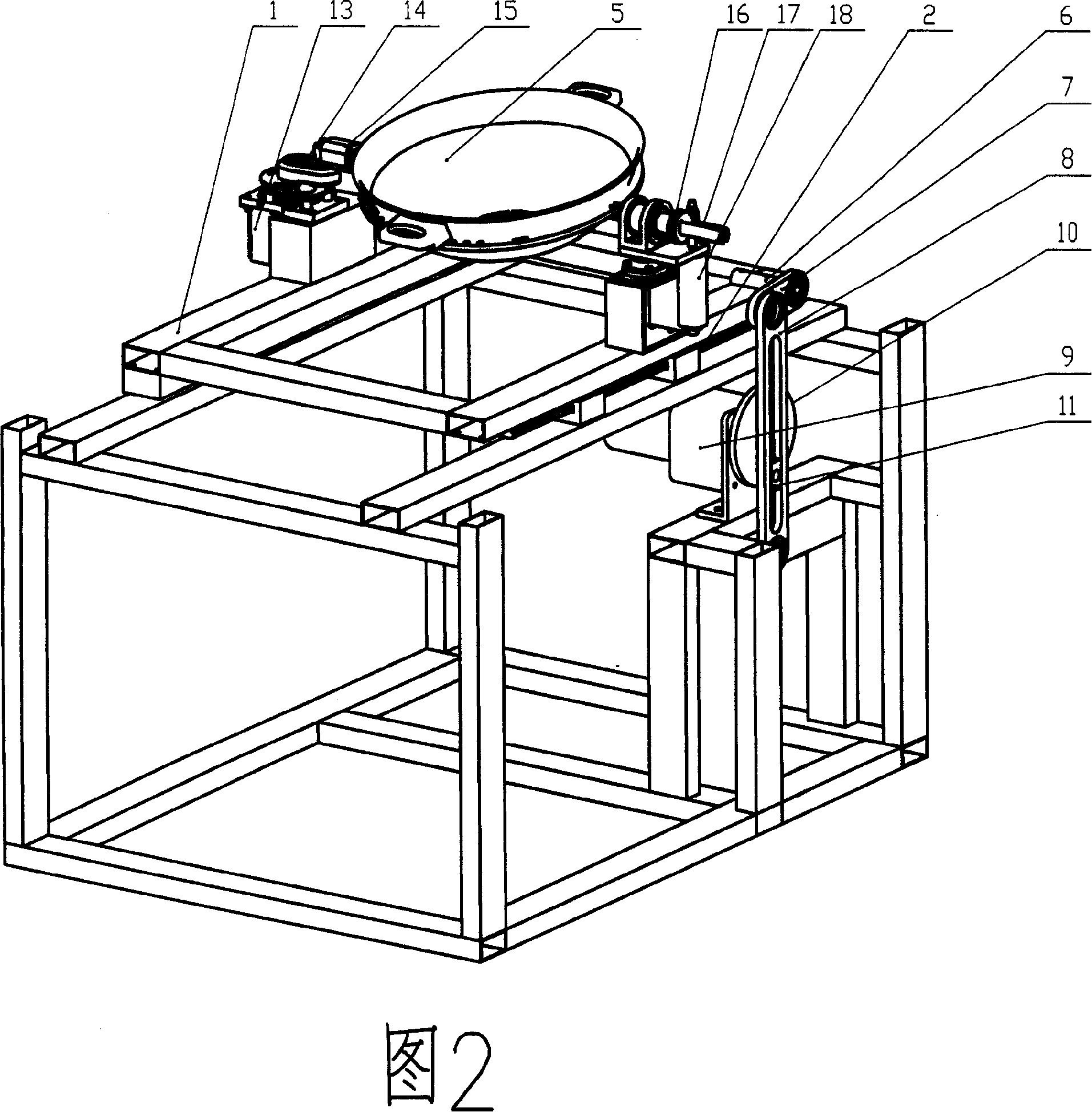
[0058] See Figure 2. The crank guide mechanism of the device is the same as that shown in FIG. 1 , but the angle adjuster 4 in FIG. 1 is replaced with a motor (second driving device) 18 and a worm gear mechanism 16 . The pot 5 is connected with the rotating shaft 17, and the motor 18 drives the rotating shaft 17 to rotate through the worm gear mechanism 16, so as to adjust and set the angle between the pot 5 and the moving direction of the pot. The motor 18 and the worm gear mechanism 16 are also the second motion mechanism (pan turning mechanism) of the pan moving device, which drives the rotating shaft 17 to rotate to realize the pan turning motion. The pot moving device also includes a third motion mechanism (pot shaking mechanism), and the crank slider mechanism 14, 15, 17 driven by the motor 13 (the third driving device) can further drive the pot 5 to move in a plane circle and shake the pot.
[0059] Specifically, the pot shaking mechanism is arranged on the translation...
Embodiment 3
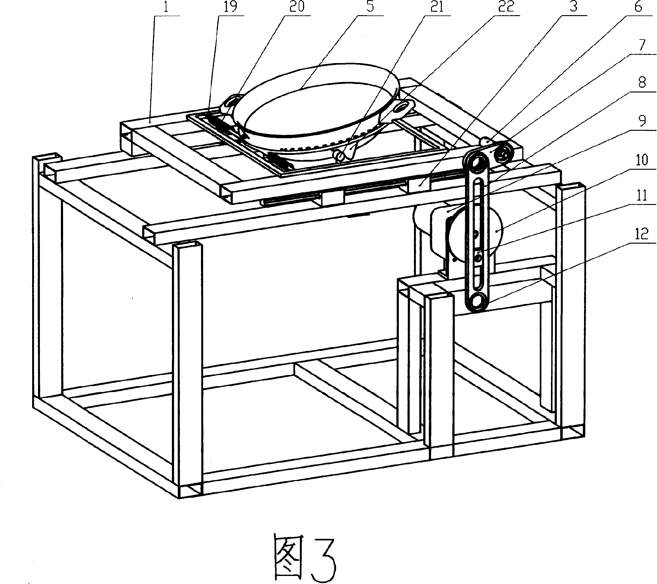
[0061] Please refer to FIG. 3 , which shows another embodiment of the pan turning mode of the pan moving device of the present invention. In the figure, the pot 5 is connected to the pivot shaft 19, and the 20 is a torsion spring for the pot to rotate and reset. 21 is a support device, which is fixedly installed on the frame, and usually the support device will be arranged at a place where a large acceleration is likely to occur, such as near the limit reverse point. 22 is a pot-turning curve device, which is connected with the pot, for example: a convex portion with a smooth curved surface extending from the bottom of the pot 5 . When the motor 9 drives the crank guide mechanism to move and drives the translation frame 1 to translate, the support device 21 (such as a smooth support shaft) contacts the smooth curved surface of the pot turning curve device 22, pushing the pot 5 around the pivot axis 19 accelerates upwards and flips over, creating a pot-turning effect.
PUM
 Abstract
Description
Claims
Application Information
 - R&D
- Intellectual Property
- Life Sciences
- Materials
- Tech Scout
- Unparalleled Data Quality
- Higher Quality Content
- 60% Fewer Hallucinations
Browse by: Latest US Patents, China's latest patents, Technical Efficacy Thesaurus, Application Domain, Technology Topic, Popular Technical Reports.
© 2025 PatSnap. All rights reserved.Legal|Privacy policy|Modern Slavery Act Transparency Statement|Sitemap|About US| Contact US: help@patsnap.com


