Profile modeling laser engraving process method and laser carving machine thereof

A laser engraving machine, laser engraving technology, applied in the direction of processing models, laser welding equipment, metal processing equipment, etc., can solve the problem of not being able to adjust the focus of special-shaped materials in real time

Inactive Publication Date: 2008-03-12
ZHEJIANG FORESTRY ACAD +1
View PDF2 Cites 62 Cited by
  • Summary
  • Abstract
  • Description
  • Claims
  • Application Information

AI Technical Summary

Problems solved by technology

[0006] In order to overcome the shortcomings of the existing laser engraving that can only perform static focus adjustment, cannot real-time focus during the engraving process, and is not suitable for special-shaped materials, the present invention provides a method that can realize dynamic focus adjustment, real-time focus adjustment during the engraving process, and realize Profile laser engraving processing method and laser engraving machine for special-shaped plane engraving

Method used


Image

  • Profile modeling laser engraving process method and laser carving machine thereof
  • Profile modeling laser engraving process method and laser carving machine thereof
  • Profile modeling laser engraving process method and laser carving machine thereof

Examples


Embodiment 1

[0031] Referring to Fig. 9, a profiling laser engraving processing method comprises the following steps:

[0032] (1) Place the workpiece to be processed on the laser engraving machine;

[0033] (2) Control the CCD laser displacement sensor of the laser engraving machine to detect the distance between the laser head and the workpiece, obtain the focus measurement data, and send it to the special system for the laser engraving machine;

[0034] (3) After the special system for laser engraving machine obtains the focal measurement data of the entire workpiece, it sends the data to the computer;

[0035] (4), the computer generates a three-dimensional topographic map of the workpiece based on the data, and under the condition of ensuring that the focus of the laser falls on the surface of the workpiece, calculates the position of the laser head of each stroke according to the processing process points, and generates X-axis, Y The control signal of the driving motor of the axis f...

Embodiment 2

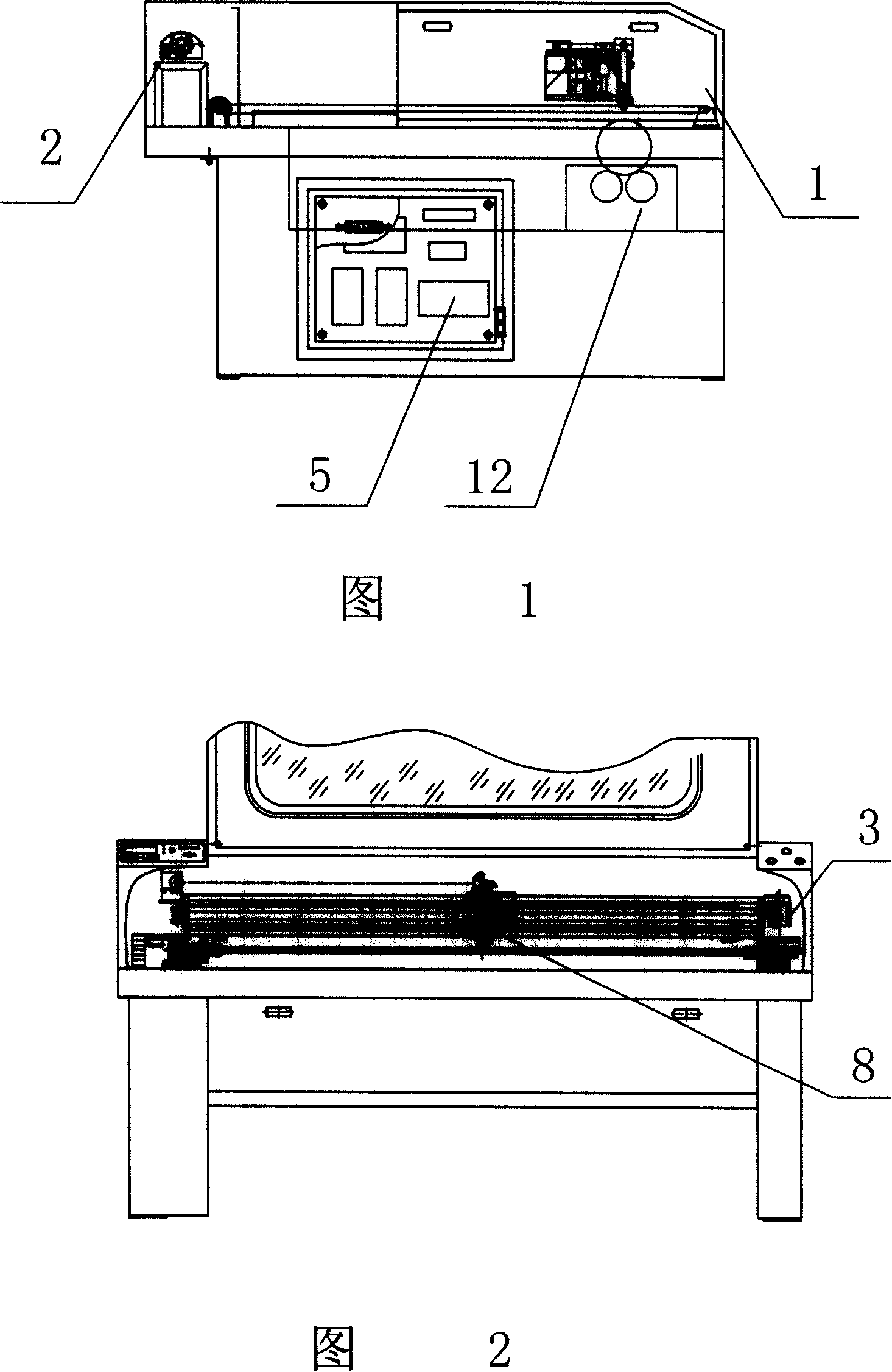
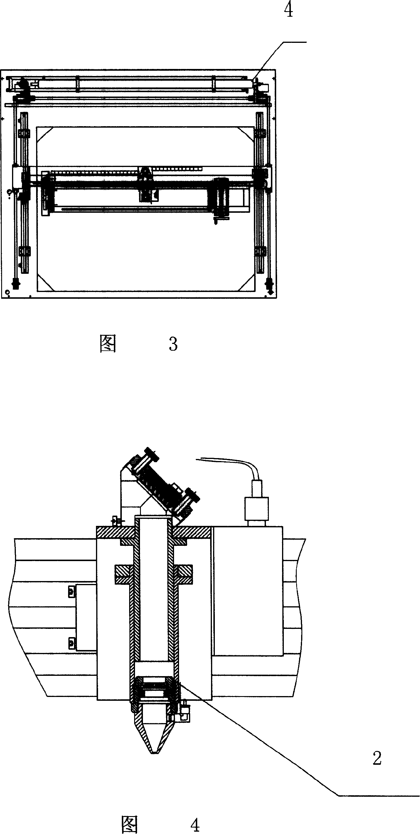
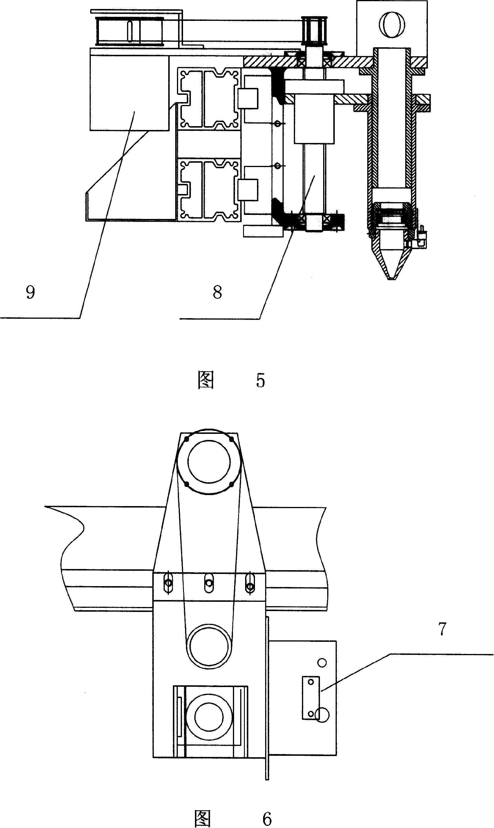
[0039] Referring to Figures 1 to 9, a laser engraving machine includes a frame 1, a laser head 2, X-axis and Y-axis flight mechanisms 3 and 4 connected to the laser head 2, and a host controller 5 for controlling profiling engraving , the X-axis, Y-axis flying mechanism 3,4 are installed on the frame 1, and the upper controller 5 includes engraving for controlling the travel of the X-axis and Y-axis flying mechanism and setting the trajectory of the laser head Processing module 6, described engraving processing module 6 is connected X-axis, Y-axis flying mechanism 3,4, and described laser engraving machine also comprises Z-axis driving mechanism perpendicular to workpiece surface, CCD laser displacement sensor 7, described Z The shaft drive mechanism includes a Z-axis transmission mechanism 8 and a control motor 9. The Z-axis transmission mechanism 8 is connected to the laser head 2, and the Z-axis transmission mechanism 8 is fixedly connected with the CCD laser displacement se...


PUM


Abstract

A method of form copying laser carving processing belongs to the laser carving processing field. The method uses a CCD laser displacement sensor to detect the distance between a laser head and a workpiece for processing to generate a three-dimensional relief map of the material for carving; a PID control arithmetic is used to control the position of the laser head to ensure that a focus of the laser falls at the surface of the workpiece for processing, so as to realize laser cutting and carving towards irregular materials. A laser carving machine is also provided, including a machine frame, a leaser head, an X-axial and Y-axial flying mechanism which is connected with the laser head, a Z-axial driving mechanism which is vertical with the surface of the workpiece, a CCD laser displacement sensor and an upper controller which is used for controlling form copying carving. The present invention provides a method of form copying laser carving processing which can realize dynamic focusing and real-time focusing during the course of carving and can realize plane carving of the irregular materials, and also provides the laser carving machine of the method.

Description

(1) Technical field [0001] The invention relates to the field of laser engraving, in particular to a laser engraving processing method and a laser engraving machine thereof. (2) Background technology [0002] Since the surface of the workpiece may not be completely flat, during processing, if the unevenness of the surface of the workpiece exceeds the focal depth of the laser (the length of the laser convergence point), it will affect the effect of laser processing. In order to solve this problem, it is necessary to timely adjust the The focal length makes the focus of the laser fall on the surface of the workpiece. Adjusting the focal length of the laser needs to obtain the current distance between the laser head and the workpiece in a timely manner. The current laser engraving machines generally can only engrave flat materials, or engrave cylinders through an auxiliary rotary engraving device, and some laser equipment also use sensor technology to achieve automatic detectio...

Claims


Application Information

Patent Timeline
Patent Type & Authority Applications(China)
IPC IPC(8): B44B1/00B23K26/04B23K26/08B23K26/36G05B15/02G05B19/04
Inventor 汪奎宏李琴任心波华锡奇朱汤军何奇江
Owner ZHEJIANG FORESTRY ACAD
Why Eureka
Try Eureka