Pin-hole type cycloid rotor pump

A cycloid rotor pump and hole-pin technology, which is applied to rotary piston pumps, pumps, rotary piston machines, etc., can solve the problems of difficult to guarantee the accuracy of eccentricity, high requirements for rotor accuracy, affecting rotor meshing, etc. Conducive to lubrication, improving mechanical efficiency and prolonging service life

Inactive Publication Date: 2008-03-12
SHANGHAI NORMAL UNIVERSITY
View PDF0 Cites 4 Cited by
  • Summary
  • Abstract
  • Description
  • Claims
  • Application Information

AI Technical Summary

Problems solved by technology

The precision of the rotor is high, and the outer rotor is a ring gear with arc teeth, which is difficult to process and manufacture
The accuracy of the eccentricity of the inner and outer rotors

Method used


Image

  • Pin-hole type cycloid rotor pump
  • Pin-hole type cycloid rotor pump
  • Pin-hole type cycloid rotor pump

Examples


Embodiment 1

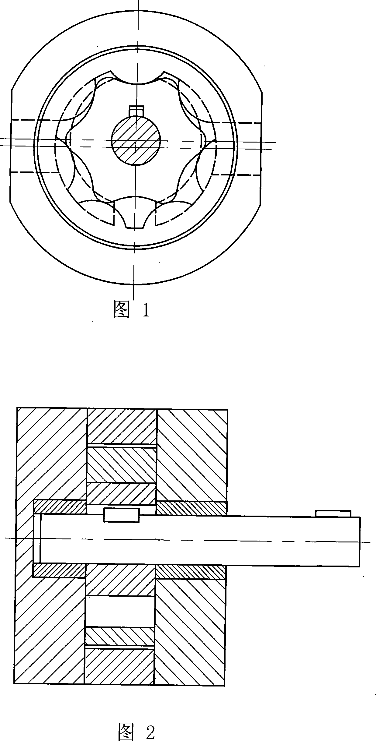
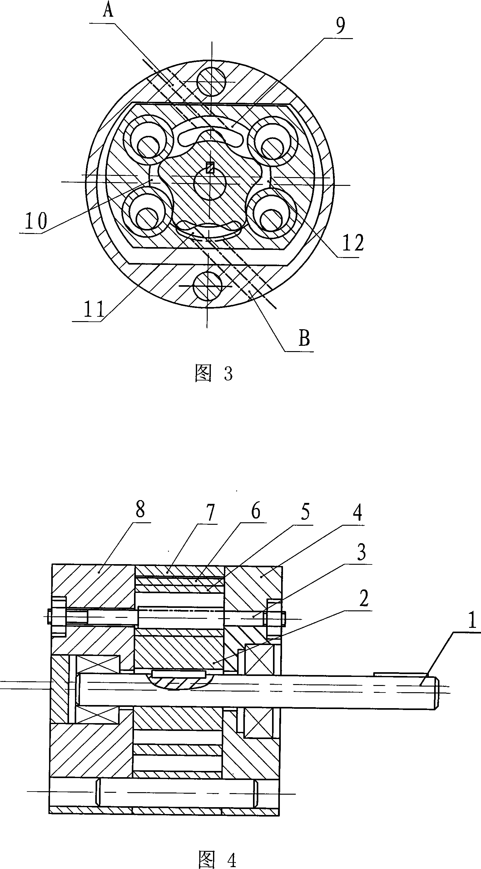
[0038] A hole pin type cycloidal rotor pump, its structure is shown in Figure 3 and Figure 4. The pump is mainly composed of a transmission shaft 1, an inner rotor 2, four pins 3, a front cover 4, six sleeves 5, a translation disc 6, a pump body 7, a rear cover 8, and oil inlet and outlet ports A and B. and other components. The transmission shaft 1 is fixedly connected with the inner rotor 2 . The inner rotor 2 is a short epicycloidal wheel; the sleeve 5 is fixed on the translation disk 6, or made into one body to form a pin wheel. The sleeves 5 are distributed on the same circle, and the pins 3 are fixed on the front pump cover, and are also distributed on the same circle, and the center of the distribution circle is concentric with the inner rotor. The two distribution circles are equal in diameter and arranged eccentrically. The pin 3 is in continuous tangential contact with the inner hole of the sleeve 5 on the pin wheel, and the pin wheel is eccentrically arranged rel...

Embodiment 2

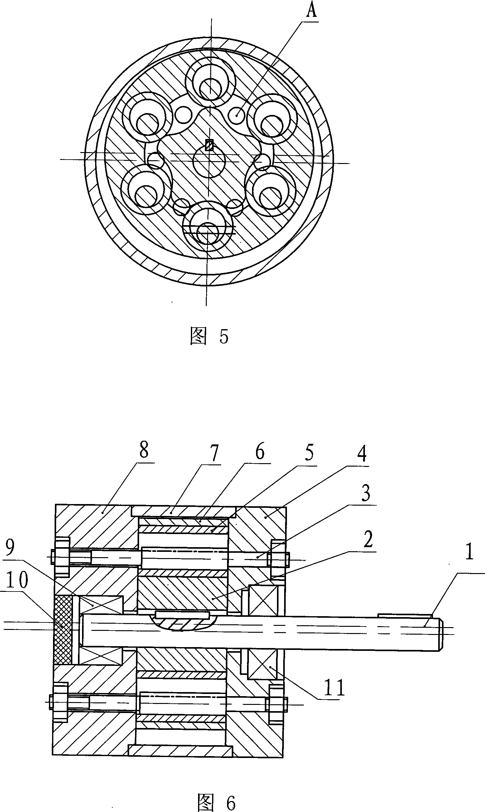
[0041] A needle-tooth cycloid hydraulic pump, the structure of which is shown in Figure 4. The hydraulic pump is mainly composed of a transmission shaft 1, an inner rotor 2, six pins 3, a front cover 4, six sleeves 5, a translation disc 6, a pump body 7, a rear cover 8, and six oil inlets and outlets. A, B and other components. The transmission shaft 1 is fixedly connected with the inner rotor 2; the inner rotor 2 is a short-width epicycloid wheel; the sleeve 5 is fixed on the translation disk 6, or made into one body to form a pin wheel. Six sleeves 5 are distributed on the same circumference, and six pillar pins 3 are fixed on the rear pump cover, and are also distributed on the same circumference, and the distribution circle center is concentric with the transmission shaft. The two distribution circles are equal in diameter and arranged eccentrically. The pin 3 is in continuous tangential contact with the inner hole of the sleeve 5 on the pin wheel, and the pin wheel is e...


PUM


Abstract

The invention is a rotor pump structure. A hole-pin type cycloidal rotor pump comprises a pump body, two pump covers respectively in the front and rear of the pump body, and a rotary shaft in the pump body center and through the pump covers; the rotary shaft is fixed to connect with an internal rotor, and an internal rotor is sleeved with a needle wheel; the internal rotor is a short-web external cycloidal gear; the center of the translational disk is a chamber, and around the cavity, at least three sleeves are embedded to form the needle wheel; the pump covers are positioned with dowel pins in the same fixing and connecting quantity of the sleeve, and with the same arrangement position as where the sleeves are embedded on the translational disk; the dowel pins are plugged into the corresponding sleeves; outside diameter of the dowel pin is smaller than inside diameter of the sleeves; the short-web outside cycloidal gears on the internal rotor, the chamber inner-wall in the center of the needle wheel, and sleeves can form a plurality of tooth chambers; and meanwhile, oil inlet and outlet ports are opened. The invention provides a rotor pump structure that can reduce flow rate fluctuation and pressure fluctuation, increase oil pressure, improve hydraulic pump stability, improve and increase comprehensive performances of hydraulic pumps.

Description

(1) Technical field [0001] The invention relates to a hydraulic transmission device, in particular to a rotor pump structure for providing pressure liquid. (2) Background technology [0002] As known, the hydraulic oil pumps of the prior art include gear pumps, vane pumps, plunger pumps, and cycloidal rotor pumps, each of which has advantages and disadvantages. [0003] Gear pumps have problems such as "trapped oil", unbalanced radial hydraulic pressure, and large flow pulsation. "Trapped oil" causes a large additional load on the gears and bearings, the bearing life is short, and the oil pump efficiency is low. In addition, "trapped oil" will also increase the oil temperature, which will easily generate air bubbles, and the bursting of air bubbles will cause loud noises. The unbalanced radial hydraulic pressure causes the gear shaft to be bent, the radial clearance of the gear in the oil suction chamber becomes smaller, and the gear and the inner cavity of the pump body a...

Claims


Application Information

Patent Timeline
IPC IPC(8): F04C2/10
Inventor 林菁
Owner SHANGHAI NORMAL UNIVERSITY
Why Eureka
Try Eureka