Interference canceling method for co-frequency co-time slot duplexing

An interference cancellation, co-frequency simultaneous technology, applied in the direction of duplex signal operation, transmission system, electrical components, etc.

Active Publication Date: 2008-03-12
北京和宽科技有限公司
View PDF0 Cites 48 Cited by
  • Summary
  • Abstract
  • Description
  • Claims
  • Application Information

AI Technical Summary

Problems solved by technology

The above two duplex methods sacrifice frequency resources and time resources in isolating uplink and downlink respectively

Method used


Image

  • Interference canceling method for co-frequency co-time slot duplexing
  • Interference canceling method for co-frequency co-time slot duplexing
  • Interference canceling method for co-frequency co-time slot duplexing

Examples


Embodiment Construction

[0022] The present invention will be described in further detail below in conjunction with the accompanying drawings, but the scope of the present invention is not limited in any way.

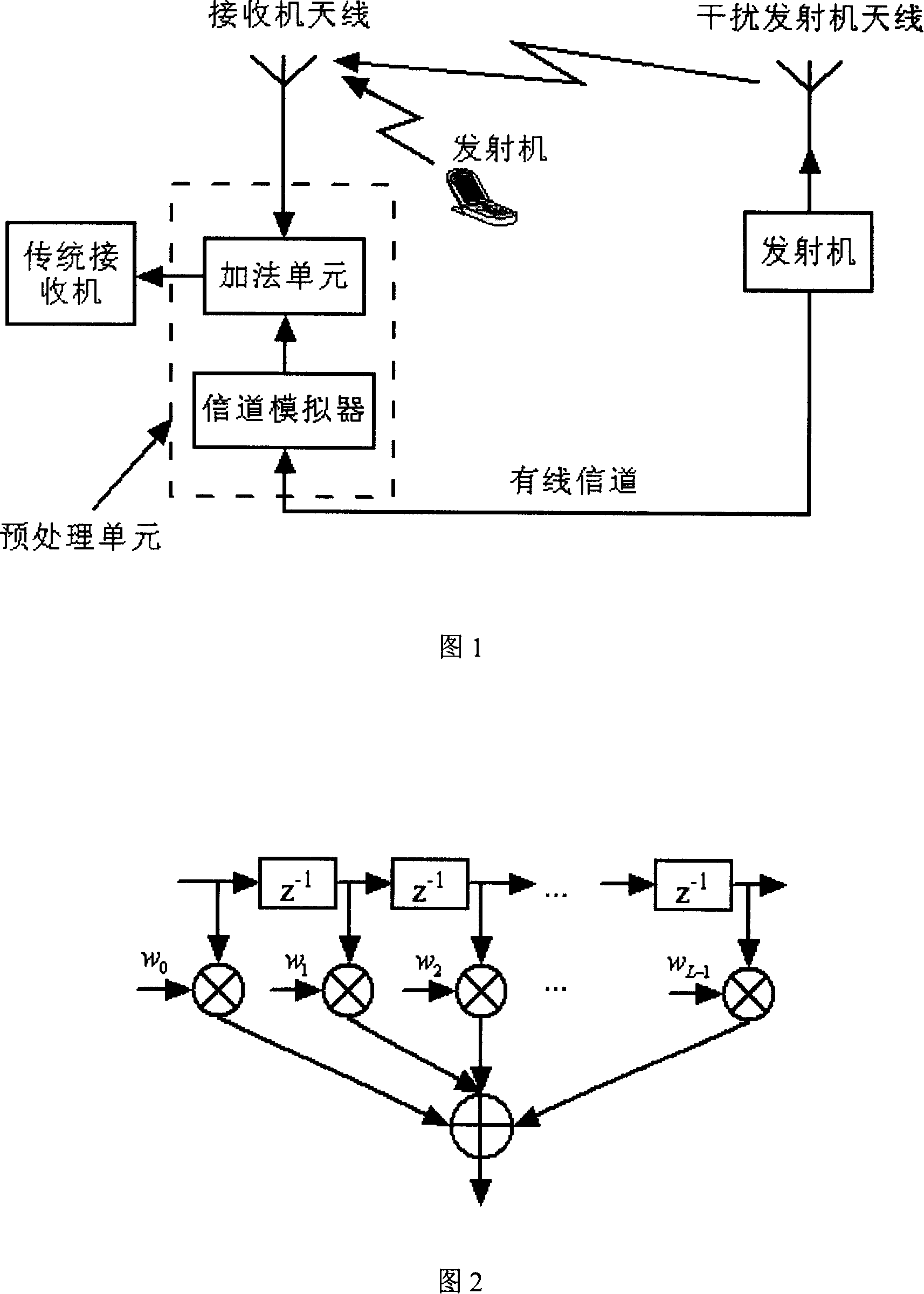
[0023] An example system is shown in Figure 1. The key to implementing the above-mentioned interference elimination technology is to accurately obtain the filter parameters in the channel simulator, and transform the jamming transmitter signal transmitted through the wired connection into the interference signal on the air interface through the channel simulator. The signals are approximately consistent, so the interference signal in the receiver signal can be completely eliminated as much as possible by using the subtraction operation. The method of obtaining channel parameters can be: first set up special narrow time slots with equal intervals in the time domain through the system protocol. In these special time slots, all wireless terminals in the cell stop transmitting signals, and adjacent ...


PUM


Abstract

The utility model provides a interference clearance technique, so that the up-down-going link of the wireless communication can run via the same frequency and the time-slot, so as to improve the rate of spectrum utilization. When the up-down-going channel is under the common frequency and the time-slot, the down link will interfere the up-link, namely, the base station receiver in the sub-zone is interfered by the base station transmitter of the sub-zone and the base station transmitter of the adjoining sub-zone. The utility model delivers the undesired signals to the receiver through the wired communication. The receiver is arranged with a signal preprocessing unit, so as to remove the transmitter signal interference in the radio frequency. Such signal interference is from the air interface. In addition, the utility model provides an aerial distribution rule to reduce the direct interference of the transmitter to the receiver. The interference clearance method is suitable to the duplex system with the common frequency and time-slot, so as to greatly reduce the frequency resources and time resources.

Description

technical field [0001] The invention relates to a new interference elimination method, which belongs to the field of wireless communication. Background technique [0002] A basic task of a wireless communication system is to establish a communication link between a wireless terminal and a base station. Data transmission is divided into two directions, namely: the link from the base station to the wireless terminal is called the downlink; the link from the wireless terminal to the base station is called the uplink. A system that can realize uplink and downlink data transmission is called a duplex system. Existing duplex systems include frequency division duplex and time division duplex systems. The frequency division duplex system uses different frequencies to transmit uplink and downlink data, thereby isolating the interference between the uplink and downlink. The time division duplex system uses the same frequency, but transmits in different time slots to isolate the int...

Claims


Application Information

Patent Timeline
Patent Type & Authority Applications(China)
IPC IPC(8): H04L5/14H04B1/10H04B1/12H04B1/707H04B1/7107
Inventor 焦秉立李建业
Owner 北京和宽科技有限公司
Why Eureka
Try Eureka