Data transmission mode setting and detecting apparatus and method
A data transmission format and data transmission technology, applied in the field of communications, can solve the problems of wasting AT energy and increasing processing complexity, and achieve the effect of saving power and reducing complexity
- Summary
- Abstract
- Description
- Claims
- Application Information
AI Technical Summary
Problems solved by technology
Method used
Image
Examples
no. 1 example
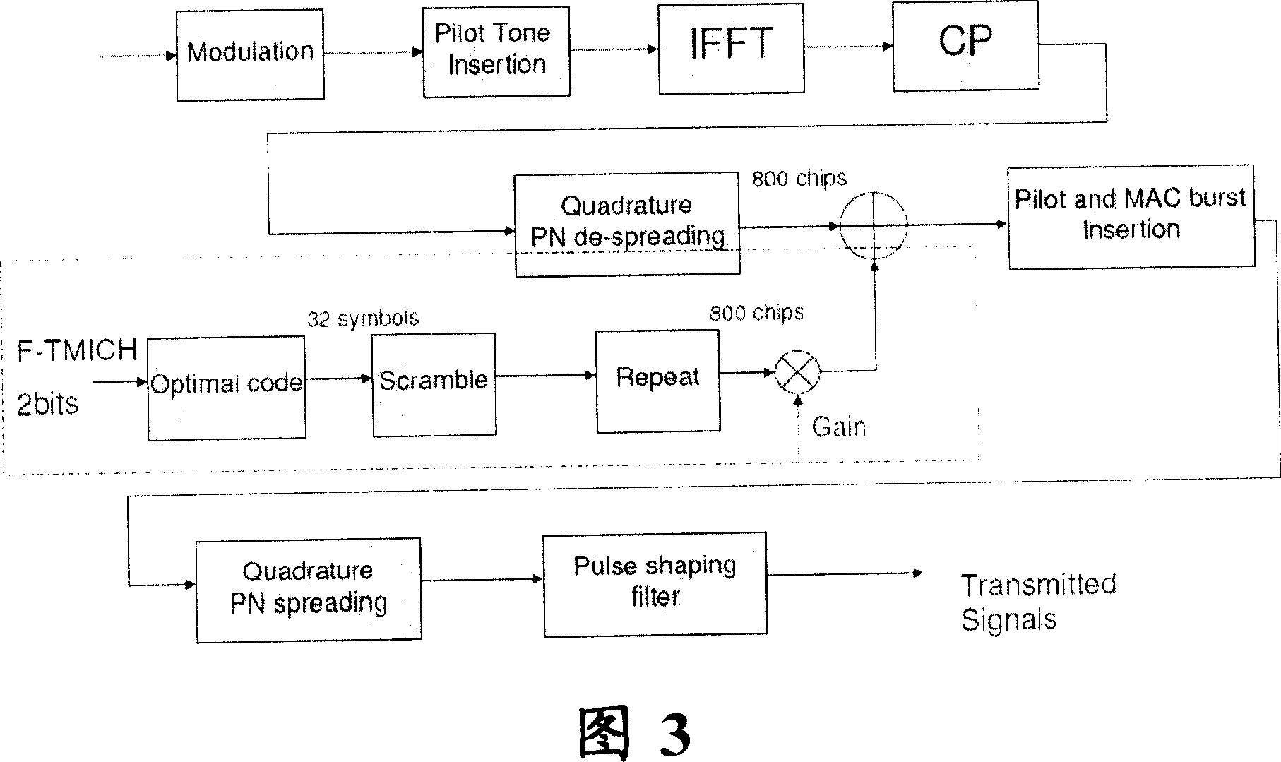
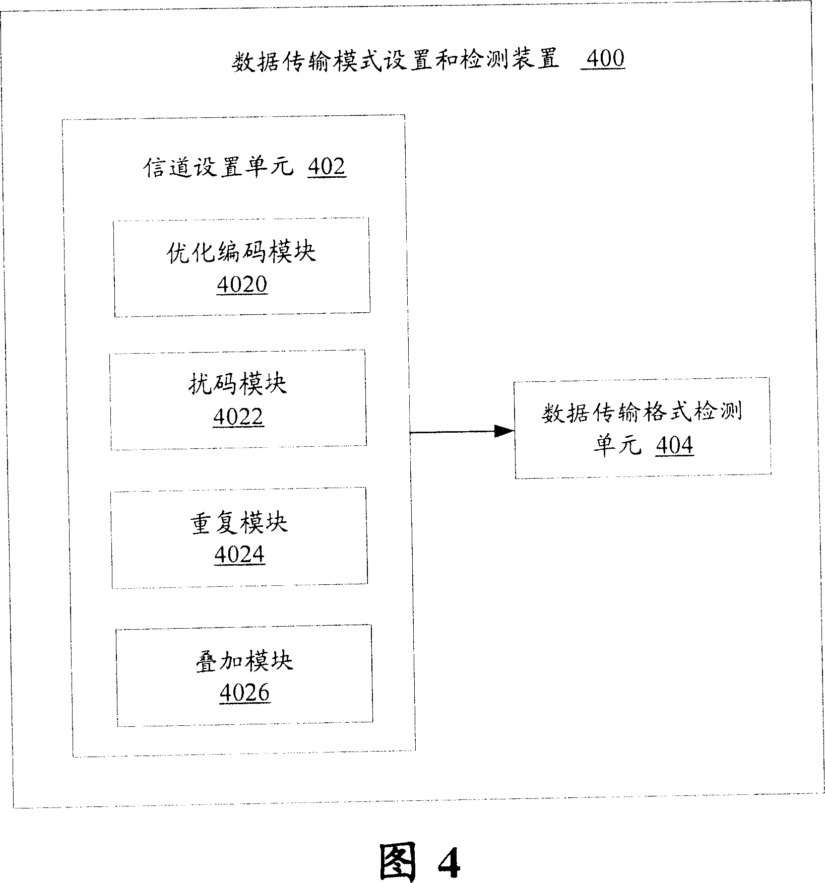
[0038]In a first embodiment according to the present invention, a data transmission mode setting and detecting device is provided. The first embodiment of the present invention will be described below with reference to the accompanying drawings, wherein FIG. 3 and FIG. 4 are a structural schematic diagram and a structural block diagram showing the device, respectively.
[0039] As shown in Figure 4, the data transmission mode setting and detection device 400 includes: a channel setting unit 402, located at the data sending end, used to set the forward transmission mode indication channel, wherein the forward transmission mode indication channel carries information for indicating data transmission mode indication information; and a data transmission format detection unit 404, located at the data receiving end, configured to analyze the indication information transmitted through the forward transmission mode indication channel, so as to detect the data transmission format.
[00...
no. 2 example
[0052] In a second embodiment according to the present invention, a data transmission mode setting and detecting device is provided. It differs from the device provided in the first embodiment in that the configuration of the channel setting unit is different, so in the following, repeated descriptions of the same parts thereof will be omitted.
[0053] The second embodiment of the present invention will be described below with reference to the accompanying drawings, wherein FIG. 6 and FIG. 7 are a structural schematic diagram and a structural block diagram showing the data transmission mode setting and detection apparatus of the second embodiment, respectively.
[0054] As shown in FIG. 7 , the data transmission mode setting and detection device 700 includes a channel setting unit 702 and a data transmission format detection unit 704 .
[0055] Wherein, the channel setting unit 702 further includes: a block encoding module 7020, used to encode the indication information; a sp...
no. 3 example
[0061] In a third embodiment according to the present invention, an apparatus for setting and detecting a data transmission mode is provided. It differs from the devices provided in the first and second embodiments in that the configuration of the channel setting unit is different, so in the following, repeated descriptions of the same parts thereof will be omitted.
[0062] The third embodiment of the present invention will be described below with reference to the accompanying drawings, wherein FIG. 9 is a block diagram showing the structure of the data transmission mode setting and detection device of the second embodiment.
[0063] As shown in FIG. 9 , the data transmission mode setting and detection device 900 includes a channel setting unit 902 and a data transmission format detection unit 904 .
[0064] The channel setting unit 902 further includes: a modulation module 9020, used to perform symbol mapping on the indication information; a gain module 9022, connected to th...
PUM
 Abstract
Description
Claims
Application Information
 - R&D
- Intellectual Property
- Life Sciences
- Materials
- Tech Scout
- Unparalleled Data Quality
- Higher Quality Content
- 60% Fewer Hallucinations
Browse by: Latest US Patents, China's latest patents, Technical Efficacy Thesaurus, Application Domain, Technology Topic, Popular Technical Reports.
© 2025 PatSnap. All rights reserved.Legal|Privacy policy|Modern Slavery Act Transparency Statement|Sitemap|About US| Contact US: help@patsnap.com


