Radio frequency signal generation and radio frequency power detection device and power detection method

A technology of radio frequency signal and radio frequency power, applied in the field of communication

Active Publication Date: 2012-02-08
ZTE KANGXUN TELECOM COMPANY
View PDF0 Cites 2 Cited by
  • Summary
  • Abstract
  • Description
  • Claims
  • Application Information

AI Technical Summary

Problems solved by technology

[0005]However, there is no technical solution to detect the quality of large quantities of RF single boards under the premise of reducing costs

Method used


Image

  • Radio frequency signal generation and radio frequency power detection device and power detection method
  • Radio frequency signal generation and radio frequency power detection device and power detection method
  • Radio frequency signal generation and radio frequency power detection device and power detection method

Examples


Embodiment 1

[0057] like Figure 4 As shown, the power detection method according to this embodiment includes the following steps: step S402, according to the frequency and power of the radio frequency signal input to the radio frequency signal power detection unit, establish a power lookup table and a frequency compensation table; step S404, according to the input radio frequency signal In the frequency compensation table, the value to be compensated is obtained through an interpolation algorithm; step S406, the control unit detects the voltage output from the power detection unit, and uses the value to perform frequency compensation on the voltage; and step S408, in the power lookup table through An interpolation algorithm obtains the input power corresponding to the RF signal.

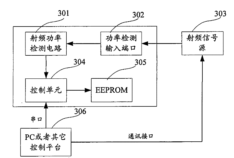
[0058] Wherein, the establishment of the power lookup table in step S402 includes the following processing: the power detection output port is connected to the radio frequency signal source, and the control plat...

Embodiment 2

[0063] like Figure 5 As shown, the method includes the following steps: step S502, switching the control unit through the radio frequency signal path, disconnecting the connection between the radio frequency power detection unit and the power detection input port, and switching the radio frequency signal generation unit to the radio frequency signal power detection unit; step S504 , the radio frequency signal generation unit outputs the set power signal, and the power of the radio frequency signal is detected by the control unit through the radio frequency signal power detection unit; and step S506, comparing the detected power with the output power of the set power signal, and processing Power so that the difference between power and output power falls within the allowable error range.

[0064] In addition, the method also includes the following processing: the control unit switches the control unit through the radio frequency signal path, and switches the radio frequency si...


PUM


Abstract

The invention discloses a radio frequency signal generation and radio frequency power detection device, comprising: a radio frequency signal generation unit, used to generate a radio frequency signal with required frequency and power; a radio frequency signal power detection unit, used to receive the radio frequency signal generated by the radio frequency signal generation unit RF signal or external input RF signal, and power detection; RF signal path switching control unit, used to control the on-off of the input / output port and the switching of the RF signal generation unit and the RF signal power detection unit; the control unit, used The interface unit is used to receive commands to control the radio frequency signal generation unit and the radio frequency signal power detection unit; and the input / output port is used to output / output radio frequency signals. By using the invention, low-cost, high-flexibility and high-precision power detection can be realized, and at the same time, the self-calibration function can be realized to obtain high-precision radio frequency signal output.

Description

technical field [0001] The present invention relates to the communication field, and in particular, to a radio frequency signal generation and radio frequency power detection device, a method for power detection using a radio frequency signal generation and radio frequency power detection device, and a radio frequency signal generation and radio frequency power detection device for radio frequency signal generation. Method for output power self-calibration. Background technique [0002] In the production process of radio frequency equipment, it is generally necessary to use radio frequency instruments to test the performance of the product. For example, when testing indicators such as board gain, output power, and receiving sensitivity of the transmitting and receiving boards of radio frequency equipment, radio frequency instruments such as signal sources and power meters (or spectrum analyzers) are required. [0003] The RF instrument can accurately measure various indicat...

Claims


Application Information

Patent Timeline
Patent Type & Authority Patents(China)
IPC IPC(8): H04W40/08H04W40/10H04B7/26H04B7/005H04B17/00H04B1/707H04B17/11
CPCY02D30/70
Inventor 张鹏闫晓艳钱崇丽吴德荣
Owner ZTE KANGXUN TELECOM COMPANY
Why Eureka
Try Eureka