Device for guiding powdery fluidic media

A technology for fluidized medium and conveying medium, which is applied in the field of devices for conveying powdery fluidized medium, especially powder paint, can solve the problems of impairing the effectiveness of pump functions and reducing the conveying efficiency of devices.

Inactive Publication Date: 2008-03-12
EISENMANN CORP
View PDF0 Cites 16 Cited by
  • Summary
  • Abstract
  • Description
  • Claims
  • Application Information

AI Technical Summary

Problems solved by technology

There are therefore many gaps in the flow path of the fluidizing medium, in which the medium can deposit, which can impair the functional effectiveness of the pump and thus reduce the delivery efficiency of the device

Method used


Image

  • Device for guiding powdery fluidic media

Examples


Embodiment Construction

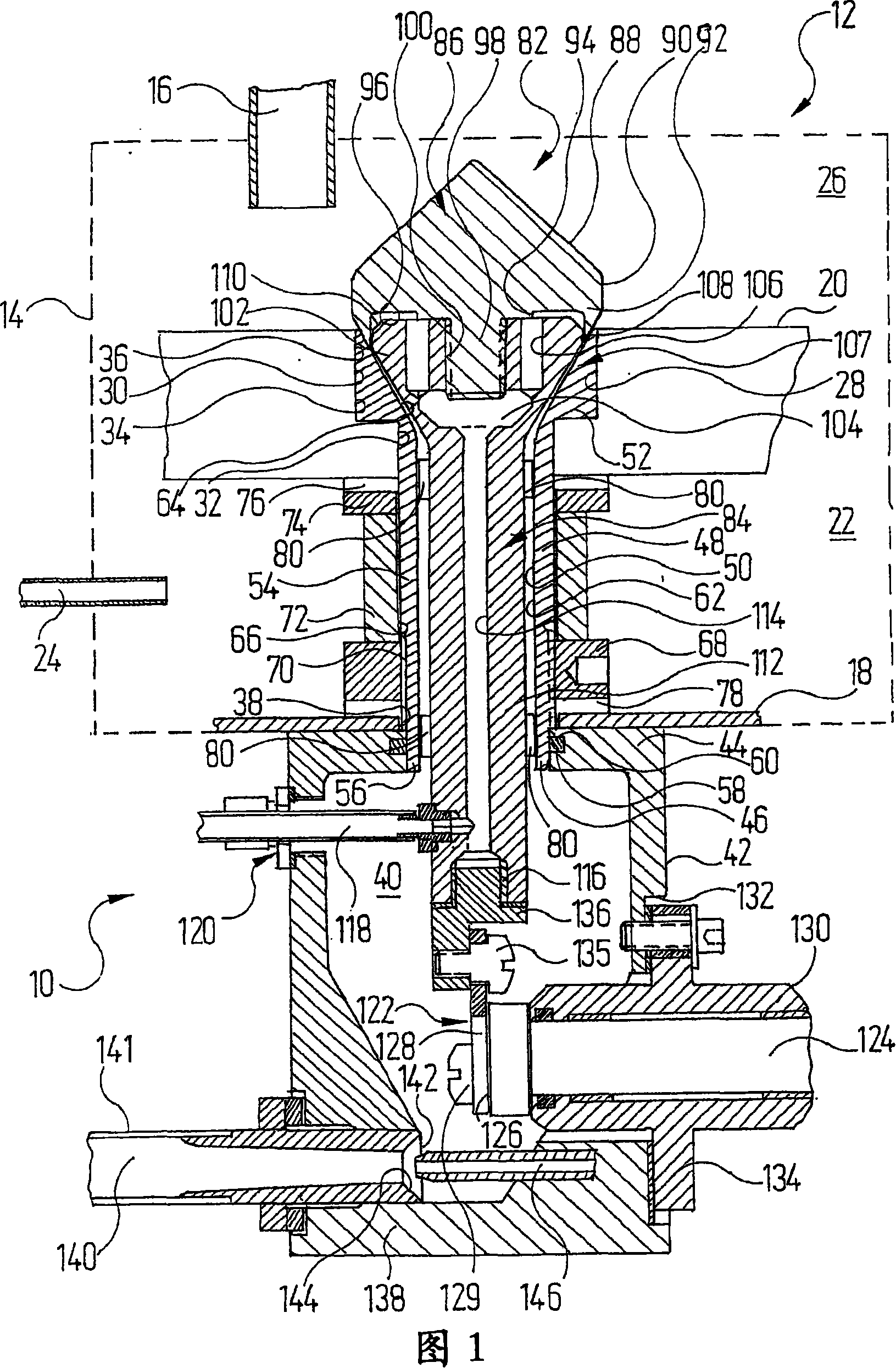
[0023] The device 10 comprises a container 12 with a housing 14 schematically indicated in dashed lines, into which powder paint is fed via a line 16 in a known manner.

[0024] At a certain distance above the bottom surface 18 of the container 12, the container 12 has a fluidization floor 20 consisting of a porous material. Compressed air is supplied via a line 24 into a pressure chamber 22 formed between the bottom surface 18 and the fluidizing bottom 20 . The compressed air penetrates through the fluidizing floor 20 into the interior 26 of the container 12 located above the floor, fluidizing the powder paint there and thus making the powder paint there flowable.

[0025] The fluidizing bottom plate 20 has a continuous stepped bore 28 with a first bore section 30 facing the interior 26 and a second bore section 32 facing the pressure chamber 22 . The second bore section 32 has a smaller diameter than the first bore section 30 . The first hole section 30 of the stepped hole...


PUM


Abstract

The invention relates to a device for guiding powdery fluidic media, in particular powder paint, comprising a receptacle (12) which is provided with an inner chamber (26) for the media which is to be guided, and from where the medium is suctioned via a connection channel (48) which can be closed by a valve body (82). The connection channel (48) and the valve body (82) comprise, respectively, an upper end area (64, 102). Said upper end areas are formed in such a manner that an annular Venturi nozzle (107) is formed therebetween which is used as a pump. The valve body (82) is inserted in a sealed manner in the end region (64) of the connecting channel (48) by means of a sealing section (92) when in the closed position thereof and comprises a conveyor gas channel (114, 104, 106, 108) which can be impinged upon by conveyor gas, through which the conveyor gas can be guided to the connection channel (48) in the vicinity of the sealing section (92), essentially, in the direction of flow of the medium.

Description

technical field [0001] The invention relates to a device for conveying powdery fluidized medium, especially powder paint, having [0002] a) a container having an inner cavity for the medium to be transported, [0003] b) A pump which draws the medium out of the container via a connecting channel which can be closed by a valve body. Background technique [0004] Such devices are used in particular in surface treatment technology, for example in the automotive industry, to feed powder paint to application devices, such as rotary atomizers. Different types of pumps can be used here. [0005] For example, by means of a known piston pump, a negative pressure is generated, whereby the fluidized paint powder in the container is sucked in and fed to an atomizer in order to spray it onto the workpiece, for example, a motor vehicle body. [0006] The conveying of the powder paint here takes place under strong mechanical action, so that heat generation and wear of the individual po...

Claims


Application Information

Patent Timeline
Patent Type & Authority Applications(China)
IPC IPC(8): B05B7/14
CPCB05B7/1404
Inventor E·希恩A·卡特菲迪斯
Owner EISENMANN CORP
Why Eureka
Try Eureka