Engine accessory system

An accessory system and engine technology, which is applied in the direction of machines/engines, mechanical equipment, etc., can solve the problems of reducing the control effect of the tensioner on the generator, and achieve the effects of improving starting performance, increasing utilization rate, and improving work stability

Inactive Publication Date: 2008-03-19
CHERY AUTOMOBILE CO LTD
View PDF0 Cites 5 Cited by
  • Summary
  • Abstract
  • Description
  • Claims
  • Application Information

AI Technical Summary

Problems solved by technology

Compared with accessories such as power steering pumps and air-conditioning compressors, generators are often the accessories with the largest dynamic moment of inertia in the entire system, but in traditional systems, power steering pumps or other accessories are also installed between the generator and the tensioner , reducing the control effect of the tensioner on the generator

Method used


Image

  • Engine accessory system

Examples


Embodiment 1

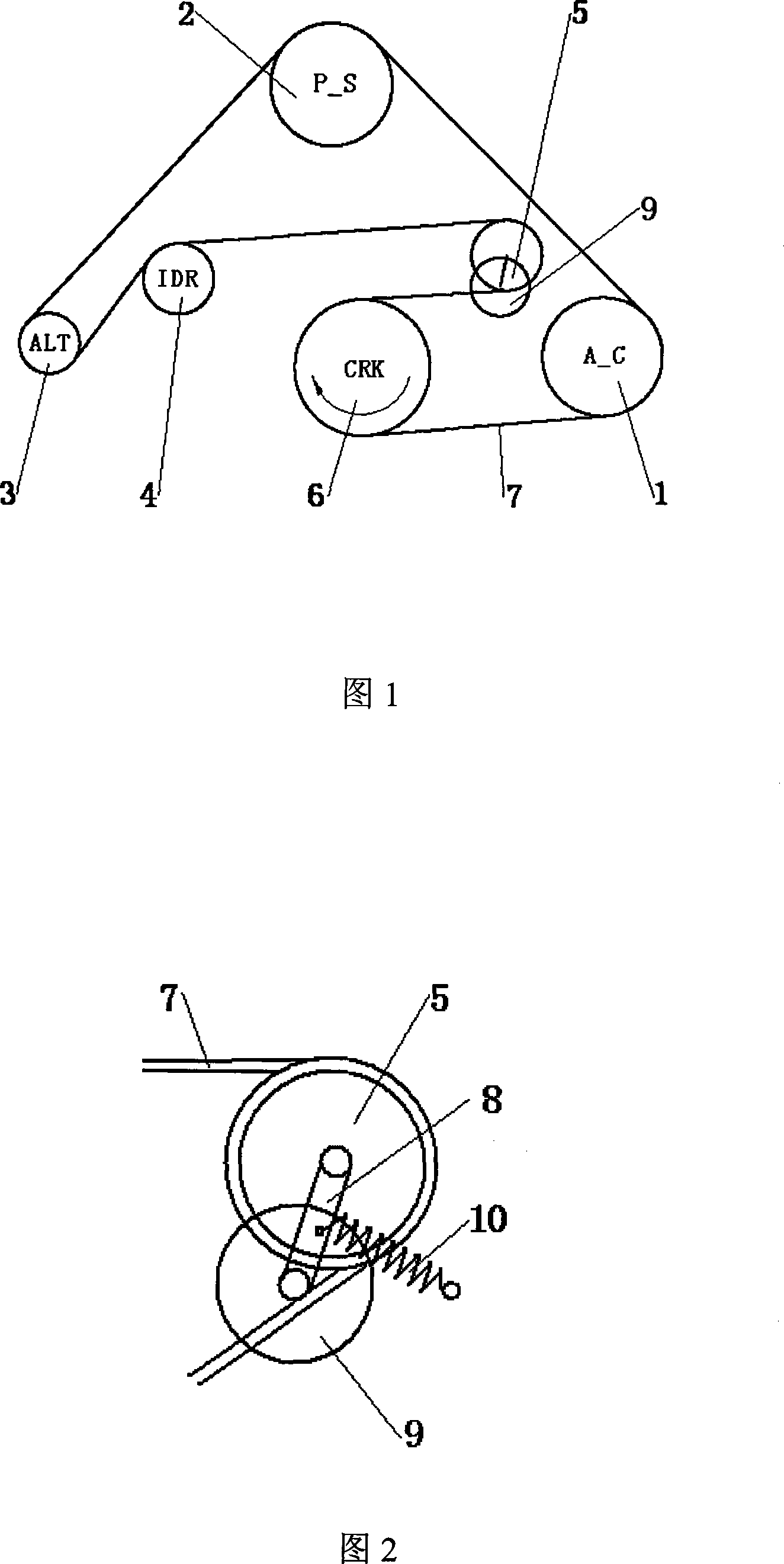
[0027] The pulley 1 of the air conditioner compressor in the transmission mechanism of the engine accessory system is arranged at a position close to the tight side of the pulley 6 of the crankshaft.

[0028] The air conditioner compressor is an accessory with a large static moment of inertia, and it is placed on the tightest side of the V-belt 7, which can improve the utilization rate of the V-belt 7 for the air-conditioner compressor, make the air-conditioner compressor enter the working state faster, and improve the The starting performance of the air conditioning system, while reducing the slip rate, thereby improving the performance of the air conditioning system.

Embodiment 2

[0030] Based on Embodiment 1, the transmission mechanism of the engine accessory system, from the loose side to the tight side of the crankshaft pulley 6, according to the tension pulley 5, idler pulley 4, generator pulley 3, power steering pump belt Set the order of wheel 2 and air conditioner compressor pulley 1.

[0031] An automatic tensioning mechanism is installed in the accessory system, and the automatic tensioning mechanism must be placed on the loosest side of the V-ribbed belt 7. The accessories next to the tensioning mechanism are generators, power steering pumps, air-conditioning compressors, and air-conditioning compressors. Be sure to place it on the tightest edge of the V-belt 7.

[0032] The moment of inertia of the power steering pump is in the middle of all accessories, so it is arranged between the generator and the air-conditioning compressor, which can meet the requirements of the steering system in general.

[0033] Arrange the automatic tensioning mech...

Embodiment 3

[0035] Based on Embodiment 1 and Embodiment 2, the tension pulley 5 is arranged on the outer circumference of the V-ribbed belt 7, so that the V-ribbed belt 7 forms an indentation there. Since the tension pulley 5 is arranged next to the crankshaft pulley 6 and is on the loosest side of the V-ribbed belt 7, the tensioning pulley 5 makes the wrap angle of the V-ribbed belt 7 larger on the crankshaft pulley 6 , making the transmission more efficient.


PUM


Abstract

The invention discloses an engine accessory system. The transmission mechanism comprises an air condition compressor belt pulley, a power steering pump belt pulley, an electrical generator belt pulley, an idle pulley and a tightening pulley, and is connected with a crankshaft pulley through a multi-wedge belt, the crankshaft pulley as a driving pulley realizes the belt transmission, the tightening pulley is positioned on the casing body of the engine through an automatic tension mechanism, and is arranged at the position adjacent the loose side of the crankshaft pulley. By adopting the technical proposal, an electrical generator with a bigger dynamic rotation inertia is controlled perfectly while the tightening pulley maintaines a system overall tension force, thereby the utilization ratio of the tightening pulley is improved, the working stability of the electrical generator is improved, and the slip ratio is reduced; the air condition compressor is placed at the tightest side of the multi-wedge belt, the startability of the air conditioning system is improved, the utilization efficiency of the accessories is improved, the vibration quantity of the belt is reduced, the noise is lowered, and the stability, as well as the total life and the efficiency of the system are improved.

Description

technical field [0001] The invention belongs to the technical field of automobile structure, and relates to the structural design of an automobile engine, more specifically, the invention relates to an engine accessory system. Background technique [0002] The engine accessory transmission system includes air conditioner compressor, power steering pump, generator and other engine accessories. The crankshaft pulley is used as the driving wheel, and the belt transmission mechanism is formed by the V-belt. In the current existing engine technology, when the engine is arranging accessories, the main consideration is the rationality of the surrounding space clearance, and less consideration is given to the impact of the relative position of the accessories on the system and the performance of each accessory itself. Therefore, the arrangement adopted cannot make each driven accessory and the whole system exert its optimal performance. [0003] The method adopted in the above-ment...

Claims


Application Information

Patent Timeline
Patent Type & Authority Applications(China)
IPC IPC(8): F02B67/06
Inventor 朱艳红
Owner CHERY AUTOMOBILE CO LTD
Why Eureka
Try Eureka