Supercharge Your Innovation With Domain-Expert AI Agents!

Vane cell pump

A vane pump and vane technology, which is applied in pumps, pump control, rotary piston pumps, etc., can solve the problems of high manufacturing cost and complex structure of pendulous slide valve pumps, and achieve the effect of simple manufacture and easy installation

Active Publication Date: 2008-03-19
JOMA POLYTEC
View PDF2 Cites 5 Cited by
  • Summary
  • Abstract
  • Description
  • Claims
  • Application Information

AI Technical Summary

Problems solved by technology

But the pendulum valve pump known from DE 195 32 703 C1 is complex in construction and therefore expensive to manufacture

Method used


Image

  • Vane cell pump
  • Vane cell pump

Examples


Embodiment Construction

[0022] For a better understanding of the invention, reference is made to the entire content of DE 10 2005 048 602, the content of which is hereby incorporated by reference.

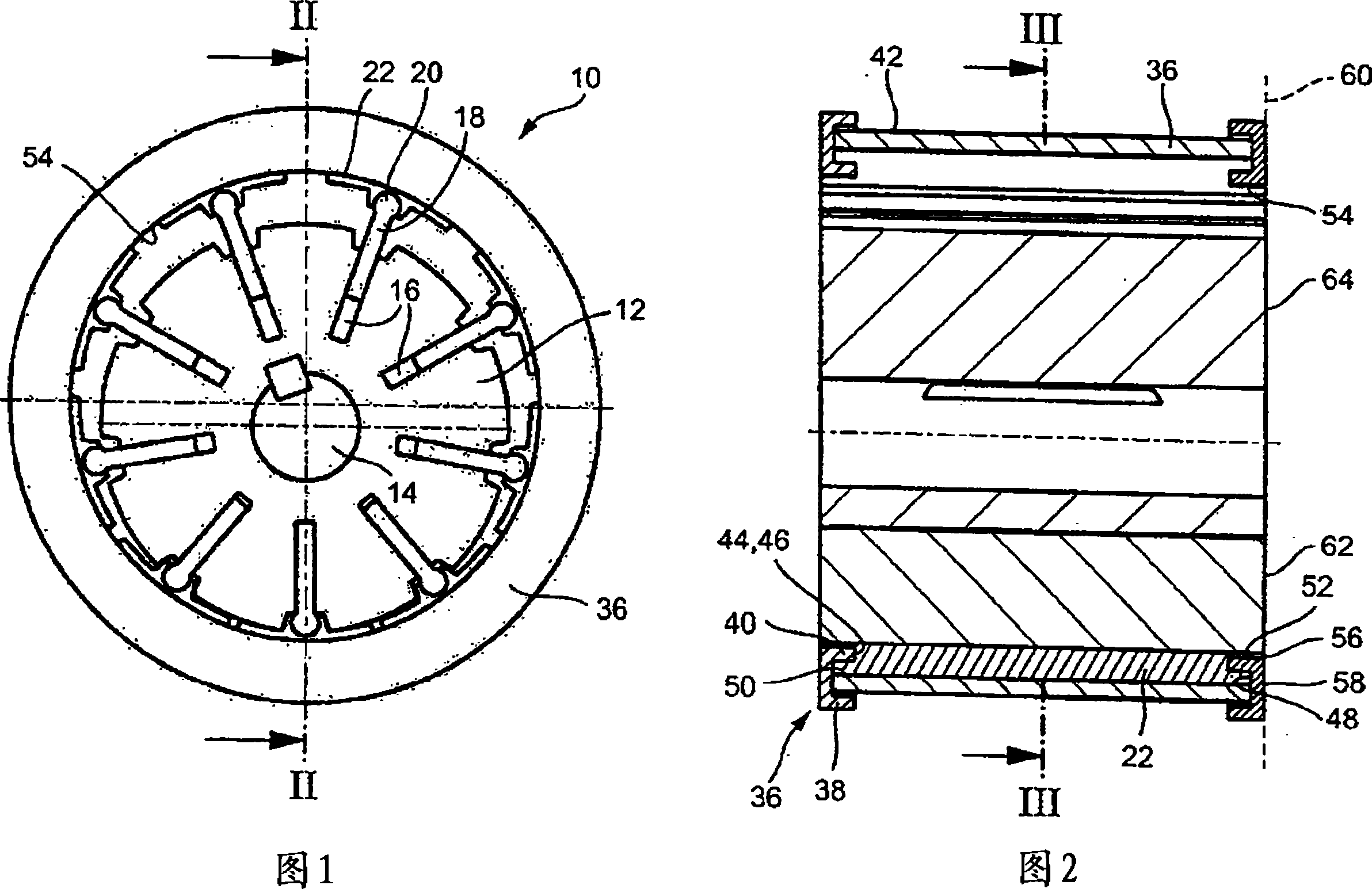
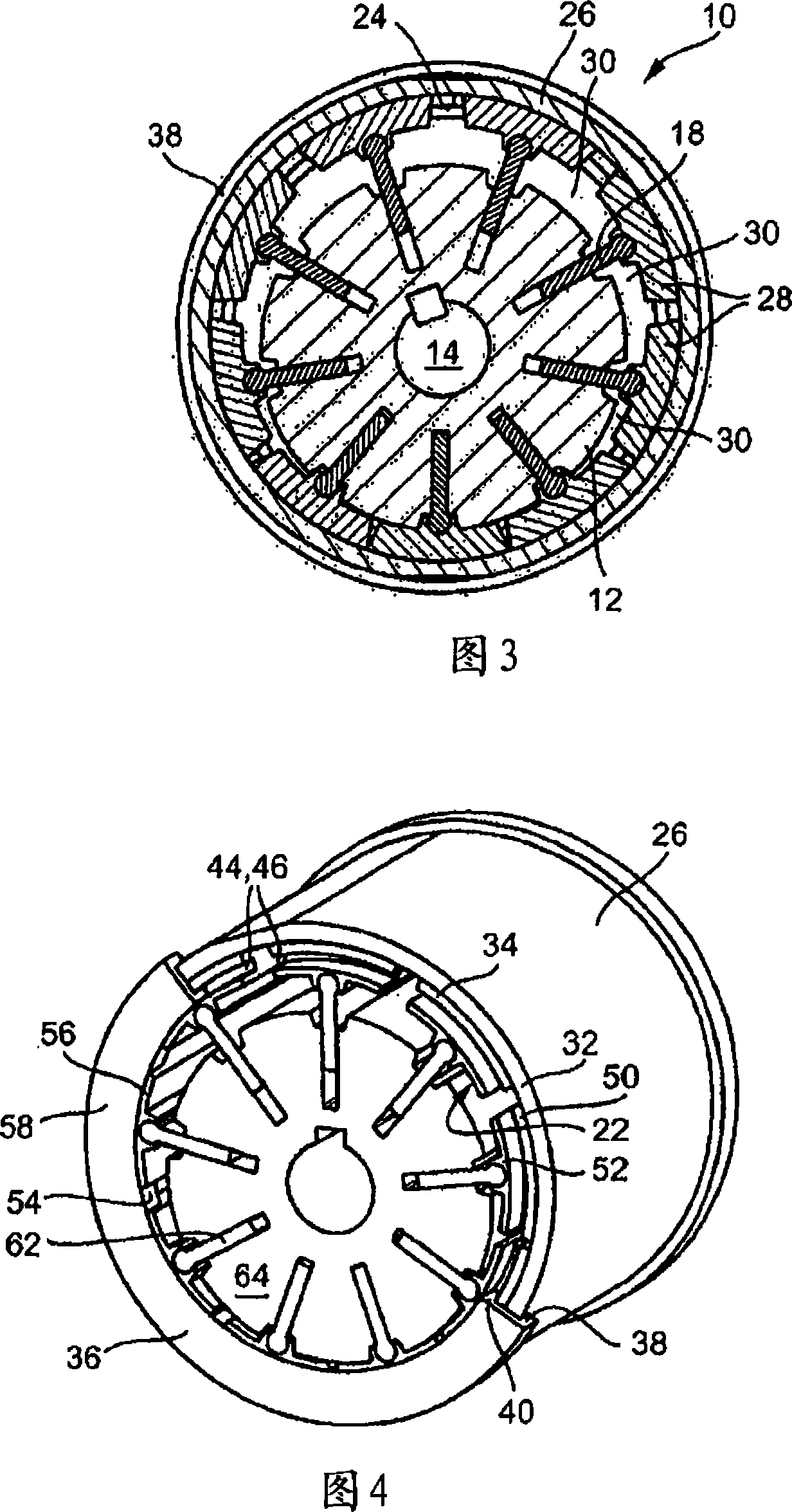
[0023] FIG. 1 shows a side view of a vane pump, generally designated 10 , having an inner rotor 12 driven by a drive shaft 14 . The inner rotor 12 has radial slots 16, and blades 18 are movably mounted in each radial slot 16 in the radial direction. The blade 18 has a thick outer end 20 to which a guide block 22 is pivotally mounted. As can be clearly seen in FIG. 3 , this guide block 22 rests on the inner peripheral surface 24 of the stator 26 . These guide blocks 22 form an outer rotor 28 which, together with the inner rotor 12 , rotates in the circumferential direction relative to the stator 26 . The blades 18, the inner rotor 12 and the guide block 22 together with the stator 26 form a working space 30, and when the inner rotor 12 rotates, the capacity of the working space expands and then shrinks. ...


PUM


Abstract

The invention relates to a vane pump comprising an inner rotor (12) and a plurality of vanes (18) pivotally fixed to an outer rotor (28) and radially movable Removably mounted in substantially radial slots (16) in the inner rotor. The outer rotor consists of guide blocks (22). The guide blocks slide along the inner circumferential surface of the stator (26) and are guided in the guide rails by their axial end faces (34). The guide rail is arranged in a guide ring (36).

Description

technical field [0001] The present invention relates to a vane pump comprising an outer rotor, an inner rotor and a plurality of vanes radially movably mounted in substantially radial slots in the inner rotor and pivotable The outer rotor is fixed to the outer rotor in a rotating manner, wherein the outer rotor is composed of guide blocks that slide along the inner circumferential surface of the stator and are guided in guide rails by their axial end faces. Background technique [0002] A vane pump with an annular inner rotor is known from DE 100 40 711 A1, in which a plurality of radially outwardly extending vane elements are accommodated so as to be displaceable in the radial direction. The radially inner ends of the blade elements rest on the torsion-proof central part, and the radially outer ends rest on the torsion-proof outer ring. The rotor is rotatable about an axis of rotation offset with respect to the central axis of the central part and the outer ring. In this ...

Claims


Application Information

Patent Timeline
IPC IPC(8): F04C2/344
CPCF04C14/226F04C2/3445F04C2/3442
Inventor 维利·施奈德
Owner JOMA POLYTEC
Features
  • R&D
  • Intellectual Property
  • Life Sciences
  • Materials
  • Tech Scout
  • Unparalleled Data Quality
  • Higher Quality Content
  • 60% Fewer Hallucinations
Learn More