Horizontal sand mill

A horizontal sand mill and spindle technology, applied in grain processing and other directions, can solve the problems of large grinding space, limited centrifugal force and high energy consumption, and achieve the effects of reducing energy consumption, improving efficiency and preventing sedimentation at the bottom of the barrel

Inactive Publication Date: 2008-03-26
ZHENGDONG INDAL KUSN CITY
View PDF0 Cites 10 Cited by
  • Summary
  • Abstract
  • Description
  • Claims
  • Application Information

AI Technical Summary

Problems solved by technology

However, due to the large grinding space, the centrifugal force generated by the rotation of the dispersion disc (blade) or the rod pin is limited, so that the grinding medium is easy to deposit on the bottom of the bucket, which greatly weakens the shear force between the material and the grinding medium, resulting in insufficient dispersion of the material and low efficiency. , high energy consumption, unsatisfactory dispersion effect

Method used


Image

  • Horizontal sand mill
  • Horizontal sand mill

Examples


Embodiment

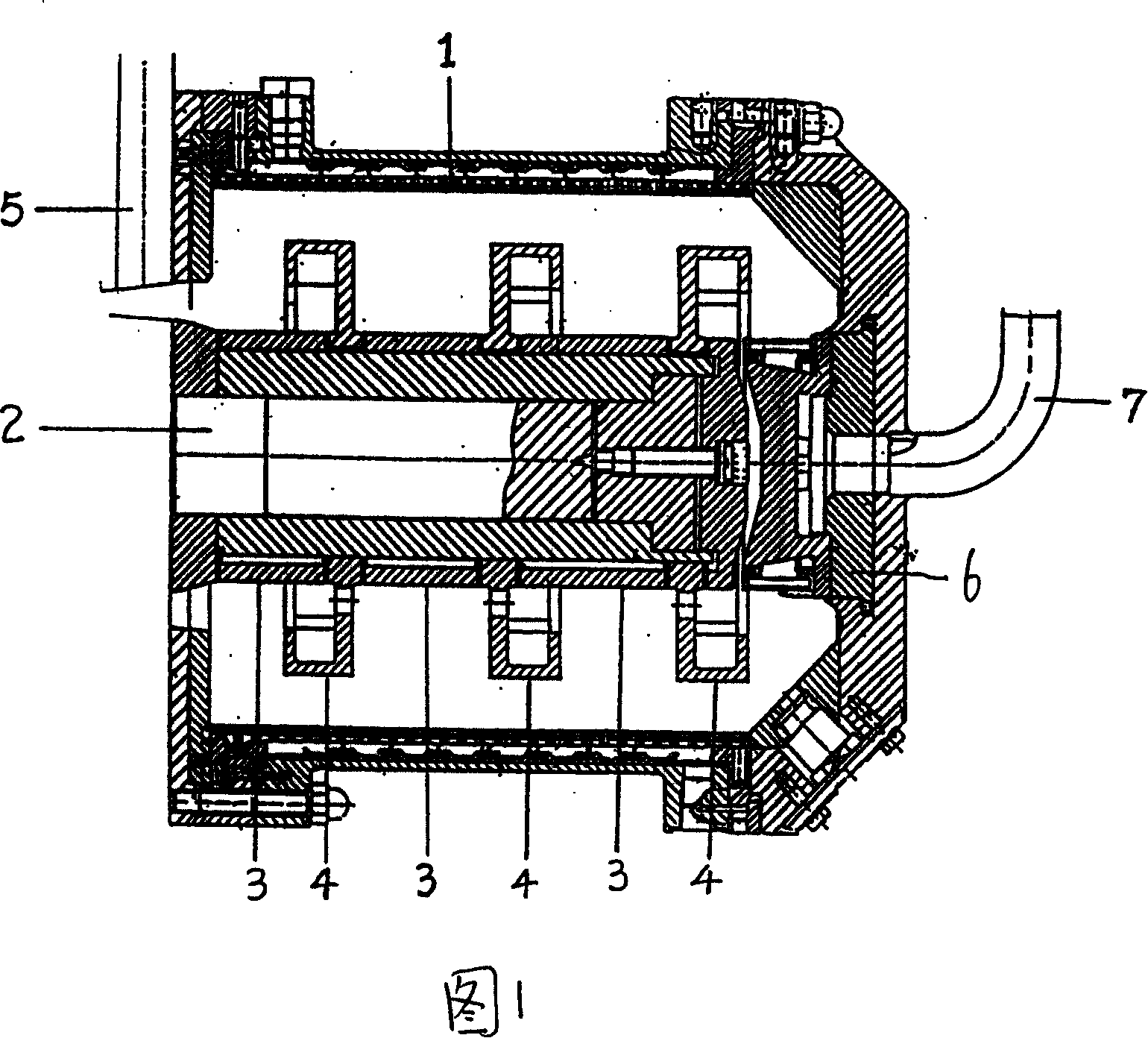
[0012] Embodiment: a horizontal sand mill, comprising a main shaft 2 and a barrel body 1, the main shaft 2 protrudes into the barrel body 1, and several dispersing turbines 4 are installed at intervals on the main shaft protruding into the barrel body.

[0013] The casing 3 is fixedly sleeved on the main shaft extending into the barrel. The radial section of the casing is square. The central hole of the dispersing turbine 4 matches the radial section of the casing. Several dispersing turbines are fixedly sleeved on the casing at intervals.

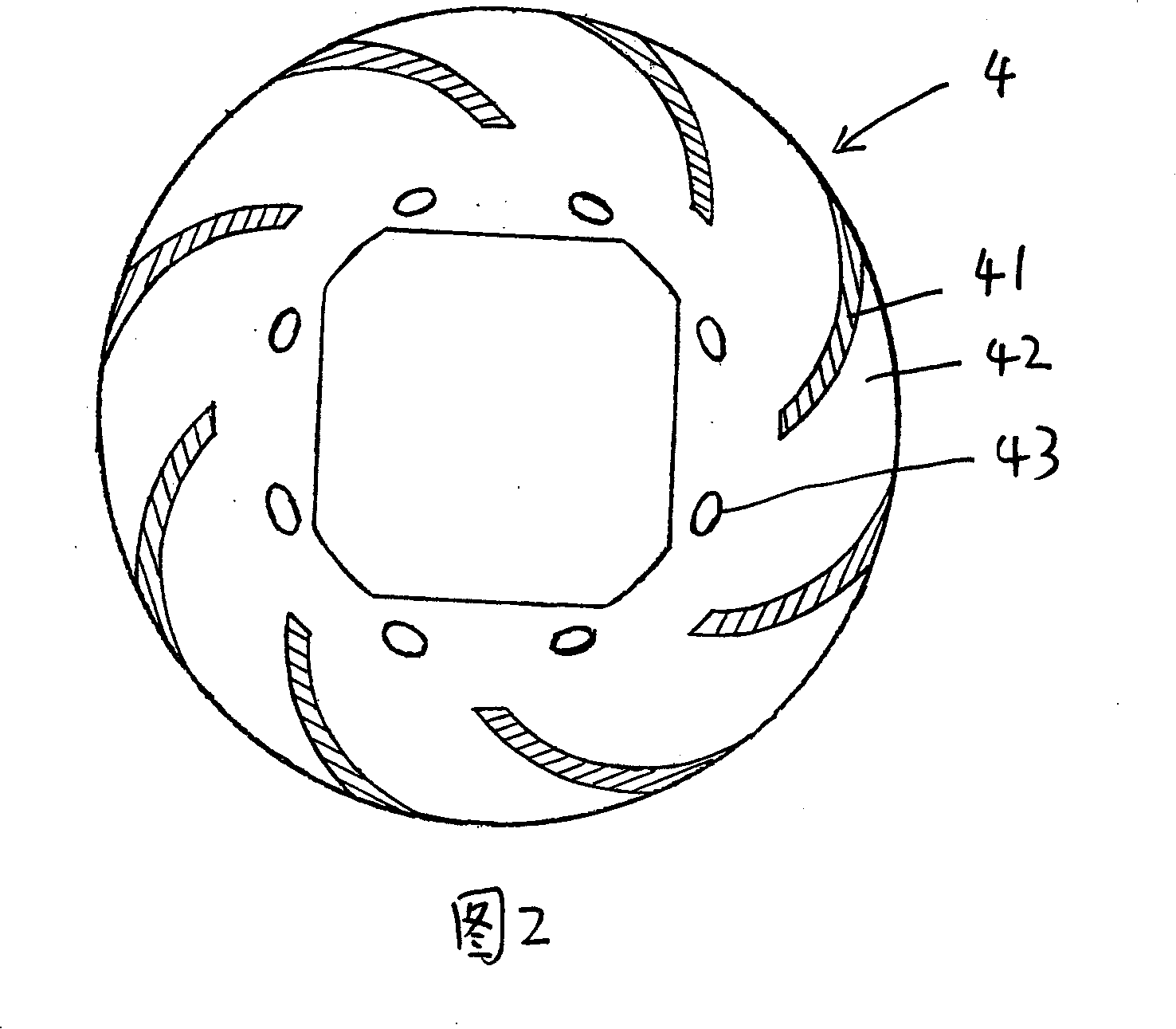
[0014] Several dispersing sheets 41 on the dispersing turbine are distributed centripetally on the dispersing disk 42, and the dispersing sheets 41 are arc-shaped.

[0015] A number of grinding medium return holes 43 are evenly spaced on the dispersing plate 42 at the inner end of the dispersing sheet 41 .

[0016] The working process of the present invention is: the material enters the grinding barrel from the feed pipe 5, and the high-sp...


PUM


Abstract

The present invention relates to a horizontal sand mill for dispersing liquid material. Said horizontal sand mill includes the following several portions: main shaft, barrel body and several dispersion wormwheels which are spaced, extended into the barrel body interior and mounted on the main shaft. Said invention also provides its working principle and its concrete operation method.

Description

technical field [0001] The invention relates to a liquid material dispersing machine. Background technique [0002] Most of the domestic original dispersing machines (sand mills) use the high-speed rotation of the dispersing disc (blades) or pins to generate centrifugal force between the material and the grinding medium, so that the material is dispersed. However, due to the large grinding space, the centrifugal force generated by the rotation of the dispersion disc (blade) or the rod pin is limited, so that the grinding medium is easy to deposit on the bottom of the bucket, which greatly weakens the shear force between the material and the grinding medium, resulting in insufficient dispersion of the material and low efficiency. , high energy consumption, unsatisfactory dispersion effect. Contents of the invention [0003] In order to overcome the above defects, the present invention provides a horizontal sand mill, which has high efficiency, low energy consumption and go...

Claims


Application Information

Patent Timeline
Patent Type & Authority Applications(China)
IPC IPC(8): B02C17/16B02C17/18
Inventor 吴国祖
Owner ZHENGDONG INDAL KUSN CITY
Why Eureka
Try Eureka